LaymarCrafts Woodturning Hints & Tips

Quick Release Flip Down Tool Rest

I often make batches of small objects such as Light/Cord Pulls, Bottle Stoppers, Key Rings Etc. that are initially Turned between Centres, then Finished and Cut Off with the standard Tool Rest/Banjo arrangement this entails constantly removing the Tool Rest and replacing it.

The ideal solution would be to have a Tool Rest that Flipped Down and out of the way when not required and then Flipped Up again without moving the Banjo or Tailstock.

In 
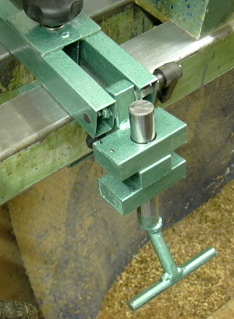
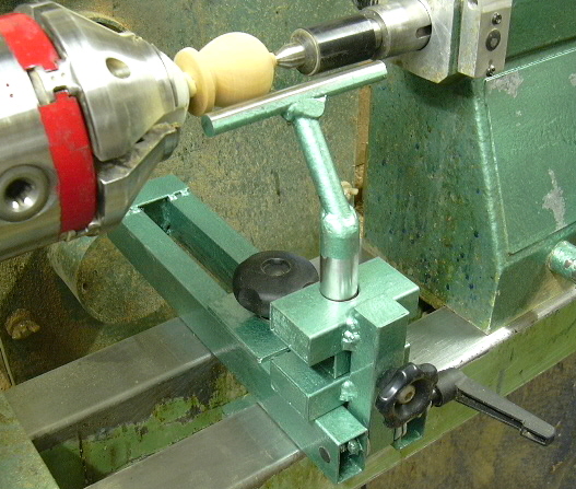
this picture you see the Tool Rest in it's normal working position.

The actual Tool Rest is the same Rest as I would use with my Standard Banjo and therefore this system could be used with any one of the numerous Tool Rests I have.

Although the Rest shown was designed specifically for small items and I describe in a later Hints & Tips how this and other Rests were made.

The Knob on the vertical pillar is for locking the Tool Post at the correct height.

The Lever to the right locks the Tool Rest Holder Assembly in place.

The large Knob at the top left of the picture is for fixing and locking the Banjo in place, when not required the Banjo can be easily removed and stored away.

The Tool Post 
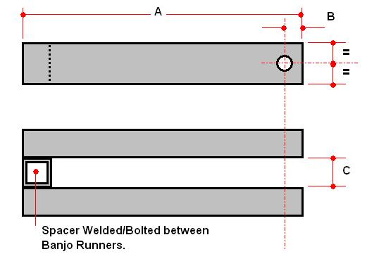
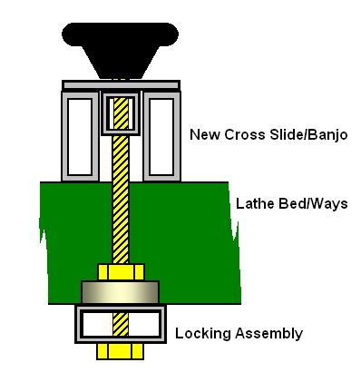
Holder is made from 50mm x 20mm [2" x 7/8"] Box Section, the upper and lower sections are welded to the vertical post with the centre section loose and this performs the clamping action on the Post, see details below.

The Banjo Cross Slide is made from two lengths of 50mm x 20mm [2" x ⅞"] to suit the Bed of your Lathe, bearing in mind that the overhang will not be an issue as this is for close in Turning.

At one end you will need to either Weld or Bolt a Spacer which will be from the same material you will be using for the Support Post that is located at the other end.

At the opposite end to the Spacer you need to drill a suitable hole for the Support Post Pivot Bolt.

Typically 9mm for an M8 Bolt, I used a M8 Lever with a Long Nut attached so that I clamped on the inner faces of the Box Section, as can be seen above, and spot welded an M8 Nut onto the opposite face.


This picture shows the Rest in the "Flipped Down" position with the Banjo remaining locked in the same position as in the picture above.


Two pieces of 50mm x 20mm [2" x ⅞"] Box Section were cut to the width of the Banjo Slide and drilled as shown to suit the diameter of the Tool Rest Post [20mm Ø].

Drilling a hole of this size can be difficult but I have found that by using a Hole Saw you can achieve a very accurate and neat hole.

The position of the hole needs to be forward of the centre line, and in my case I drilled the hole 15mm [F] in from the front edge.

These two form the fixed part of the Tool Post and were welded to a length of 25mm [1"] Box Section which has a 9mm Ø hole, to match the hole in the Cross Slide, for the Pivot Bolt.

D = 21mm which is equal to the depth of the material, + 1mm, used to make the Locking Mechanism described below.

E = 50mm the height of the Cross Slide Bars.

I first fixed the Vertical section of Box Section into the Cross Slide and made sure that it was vertical and square, I then positioned the bottom piece of 50mm x 20mm Box Section on the Cross Slide Bars and clamped it in place and then Welded it in position.

You then place the Clamping Mechanism place on the part just welded and place the second piece of 50mm x 20mm Box Section on top and clamp in place making sure that the two 20mm Holes are lined up, [use a Tool Post passing through all three holes] and again Weld it in position.
q


For the Tool Rest Clamping Mechanism I used a short length of the 50mm x 20mm Box Section again with  a 20mm Hole drilled through it, but this time on the centre line.

In the side of the piece I drilled a central hole 9mm Ø and welded an M8 Nut on the inside as shown.

You need to check that the Nut will miss the Tool Rest Post.

In the Vertical Post [above] you also need to drill a 9mm Ø hole to align with that drilled in the Locking Mechanism.

This is for the Clamping Bolt which in my case was one of the common Black Plastic type with 35mm of Screwed Rod protruding.

The final arrangement can be clearly seen in the Photo's above, the "Shear" Action of the movable center section against the fixed upper and lower parts will effectively Clamp the Tool Rest Post in place.

To fix the assembly to the Lathe I used a fairly common type of arrangement as shown in the sketch left.

The main Bolt was a M10 Coach Bolt clamped to a section of Box Section with a MDF Guide, the same width as that between the Lathe Bed Bars, at the bottom end to form a "T" bar.

At the top I used a piece of the 25mm Box Section with a top plate Pop Riveted to the top.

For locking purposes I used a M10 Female Black Plastic Knob but you could just as easily use a Lever or just an M10 Nut.

In operation the Slide generally remains in the initial set position so the clamping system does not necessarily require the more complicated "Quick Release" clamping method as any adjustment should be infrequent.

If preferred the assembly could be made so that the Locking Knob/Nut is below the Lathe Bed/Ways however as the intention was to always use this for Turning small diameter items the Locking Mechanism will never be in the way if positioned as shown.


More Tool Rest Articles I.
More Tool Rest Articles II.
More Tool Rest Articles III.
More Tool Rest Articles V.


LaymarCrafts Woodturning is the Web Site of Richard & Sheila Stapley
All Content, Articles, Pictures & Diagrams as Presented are the © Copyright of LaymarCrafts & Richard Stapley

Last update 06 May 2008
All Rights Reserved

Web Site Design & Construction by Richard Stapley.