| LaymarCrafts Woodturning | Hints & Tips |
| Angle Rest and Jigs |
Angle Rest
My reason for making an Angle Rest was born out of a need to have a means of holding Jigs or Guides for Projects that had an element of Repetitiveness involved, in particular an idea I had for a "Deep Grooving Guide".
As it turned out I have found the addition of this Rest to be most useful and is in use far more than I had ever anticipated and as such has changed somewhat from the first version I made.
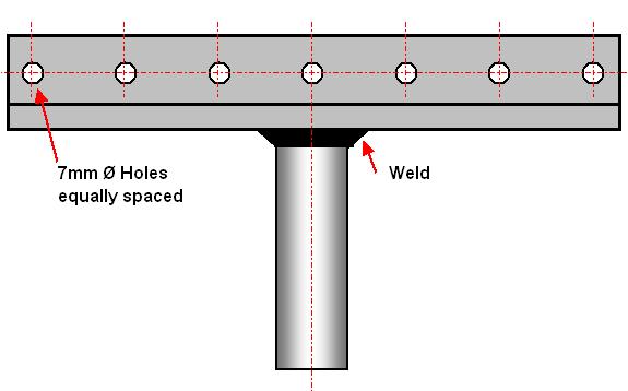
The basic Rest comprises of two main parts the Stem and the Angle, the Stem is a piece of Round MS Bar to suit the requirements of your particular Lathe, i.e. must fit the Tool Post/Banjo of the Lathe and be long enough to give the necessary Rest Height Adjustment, in my case this is 20mm Ø x 110mm long.
For the Angle Rest Part you use a suitable length of MS Angle, typically 32mm x 32mm [1¼" x 1¼"] and 250mm [10"] long, but these dimensions can be adjusted to suit your particular needs and/or the size of materials you have available.
The sketch above shows the general arrangement with the Post welded in the center of the Angle, the Holes in the Vertical Flange of the Angle are used to attach the various "Bolt On's" I have made which are described below.
These Holes, which are 6mm Clearance [7mm or 5/16" if using ¼" Screws], are equally spaced along the length of the Rest at a pitch of 32mm [1¼"] with the first Hole 13mm [½"] in from either end, again these dimensions are not critical but will be transferred to anything made to be fixed to the Rest.
The Holes are Countersunk on the Work Side Face, i.e. the side that faces the Work Piece, so that with Counter Sunk Screws you do not have a protrusion in front of the Rest that could get in the way or catch the Wood in the Chuck.
This then is the Basic Rest which can be used as an Item on its own or be used in association with the following attachments or simply as a Guide.
Grooving Jig/Guide
To start with you will need to decide exactly what Tool you will be using to Cut the Grooves and what format the Grooves are to take, i.e. Equally Spaced or Variably Spaced, because this Guide is a fixed assembly you will require a different Guide for each particular Set Up.
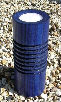
In the example shown here I have a Guide for use with a 3.9mm [approx. 5/32"] thick Parting Tool with Equal Spacing which I use to make a series of "Grooved" Candle Holders.
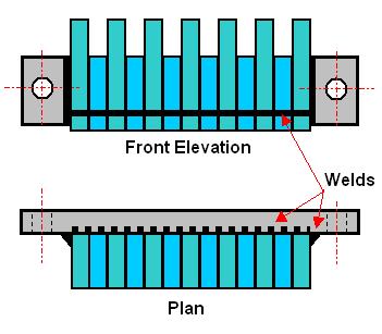
First you need some MS Bar with a thickness of 4mm [approx 3/16"] this will when assembled give a free but not sloppy Groove into which the Parting Tool will Slide.
You will require approximately 510mm [20"] of 19mm x 4mm [¾" x 3/16"] MS Bright Bar cut into 7 lengths at dimension "A" and 6 lengths at dimension "B" which in my case were 45mm [1¾"] and 32mm [1¼"] respectively.
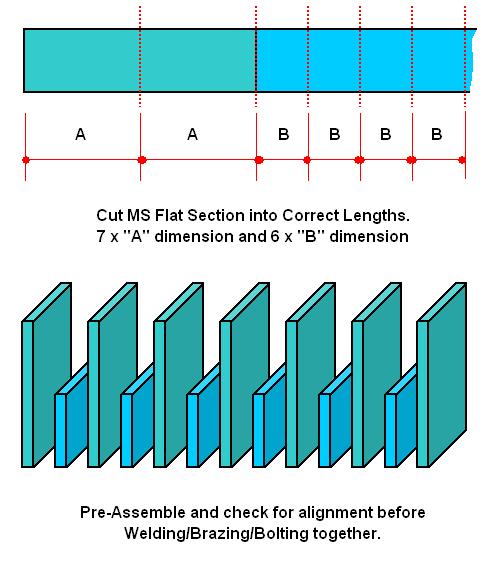
Dimension "B" is equal to the Flange dimension of the Angle used to make the Angle Rest [32mm 1¼"], this will ensure that when in position the Tool Rest part of the Angle Rest and the Support part of the Groover Guide are on the same level.
Dimension "A" [45mm 1¾"] is equal to "B" + the width of the Parting Tool - 2mm [approx. 1/16"] this will ensure that their are no Traps for the Wood Shavings, created during the Cut, and therefore "Bind" the Tool in the Guide.
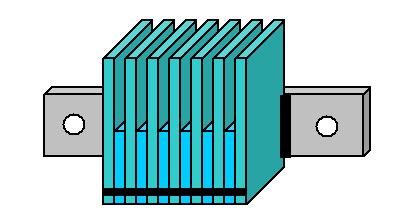
Once cut, all the pieces should be Square and Flat with all edges De-Burred and corners rounded before assembling the parts as shown below and clamped either in a Vice or with a G Clamp to test that the Parting Tool will move freely in each of the Recesses.
You will now require a Back Plate for attaching the Guide to the Angle Rest and for this I used a 120mm x 25mm x 6mm [4¾" x 1" x ½"] piece of MS Bar with two Holes drilled and tapped for M6 [¼"] at 96mm [3¾"] centers, generally as shown below.
You are now in a position to carefully assemble the Guide and although I chose to Weld mine you could possibly Braze the assembly or, as I did for an earlier version, Bolt the assembly together.
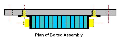 |
For this you will require two pieces of the 32mm Angle and an extended back plate. By drilling very carefully a hole through each of the "Leaves" of the Guide in exactly the same place and also in the two pieces of Angle you can Bolt the assembly together, generally as shown, the Bolted Assembly is Screwed to the Backplate with two Countersunk Screws. |
If you are going to Weld the assembly you first need to have the "Leaves" clamped together and Grind a "V" Notch low down on the front of the Assembly and then Weld along this notch to fix the Leaves in place, now clamp the Back Plate in position so that the Top of the Backplate and the Bottom of the Recesses are level.
When this is done you should have an Assembly with the Leaves just protruding below the Backplate this is where you now do the second Weld [shown dotted in sketch below], finally Weld down either side of the assembly as shown.
If you are Brazing the Assembly then you should follow the same procedure bearing in mind that you will require far more Heat and therefore the Assembly should be firmly Clamped to prevent any distortion and allowed to Cool Slowly.
|
|
|
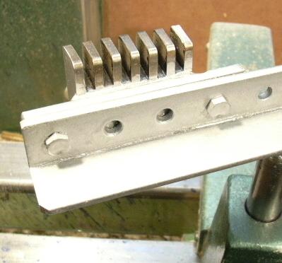
The Finished Article bolted to the Angle Rest. |
A" Grooved" Candle Holder. |
![]() More Tool Rest Articles I.
More Tool Rest Articles I.
![]() More Tool Rest Articles II.
More Tool Rest Articles II.
![]() More Tool Rest Articles IV.
More Tool Rest Articles IV.
![]() More Tool Rest Articles V.
More Tool Rest Articles V.
|
|
|
LaymarCrafts Woodturning is the Web
Site of Richard & Sheila Stapley Last update 06 May 2008
|
|
Web Site Design & Construction by Richard Stapley. |