 |
| LaymarCrafts Woodturning | Hints & Tips |
| Deep Boring System PtII |
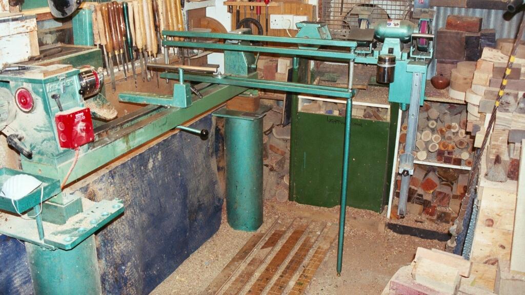
The Picture below shows the Trap complete with its Support Leg which is used when the Lathe Head is at an angle and the Trap is clamped to the Lathe Bed at one end.
|
The Trap was basically made from 4 lengths of 1" Square Steel Tube and M12 Screwed Rod and the Support Leg main component is a 1" Ø piece of Steel Tube although it could have just as easily have been from the same material as the Trap.
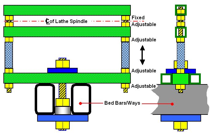
In the Diagram you can see the general concept of construction I used to form the Trap, for dimensions you will need to take certain measurements from the Lathe, the most important being the Height from the top of the Bed [Ways] to the Centre Line of the Lathe Spindle as this will be the basis for the Length of Screwed Rod required.
Firstly I cut 4 x 1m [39"] lengths of the 1" sq. Tube to form the Support Base and Trap, you will also require 2 lengths at 40mm [1½"] long approximately.
You now require 2 lengths of M12 [½"UNC] Screwed Rod which need to be to a length calculated as follows:-
| Spindle Height + 1" + half the thickness of your Boring Bar + thickness of 1 Nut + 2" |
| In my case this equated to:- 200mm + 25mm +12.5mm +12.5mm + 50mm = 300mm [8"+ 1" + ½" + ½" + 2" = 12"] |
This is not critical but too little will mean you may have a lack of adjustment and also have nowhere to attach the Support Leg [if you do not intend to use this part then you can reduce the length by 1"].
You also require 12 Nuts + 2, for the Support Leg, to suit the Screwed Rod used and 8 Washers.
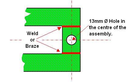
If we start with the Top Bar first this requires 2 Holes drilled in it, these to be the Standard Clearance Hole for the M12 Screwed Rod [ or which ever size you use], one hole at either end is required, 12.5mm [½"] in from the end of the Tube, note this type of Tube is often a Seam Welded Tube and therefore a "Ridge" will be present on the inside of the Tube you are best advised to not Drill through this Tube Wall as the Nuts you will be using will not sit square.
The Bottom of the Trap also requires Holes of the same size and in the same position but this time they need to be drilled right through the Tube not just through one wall as for the Top Bar, again look for the Seam Weld.
The Support Base or Bottom Bars which supports the Trap, and is also the part that is Clamped to the Lathe, was constructed from the 2 final lengths of Tube and the two short pieces as shown right. You can either Weld or as I did Braze with Silver Solder, I found that you can buy an Item called a Turbo Torch* which uses Map Gas and with care you can achieve a sound joint on material of this size.
* Most Car / Auto Retailers have these as do a number of DIY Places. |
|
Now you are ready to assemble the Trap, first you will need to fit the Screwed Rod into the Top Bar by inserting a Nut into the Tube into which you will Screw a length of Rod, you will need to File/Grind two opposite sides of the Nut so that it is a good fit in the Tube, and this will prevent it from turning.
Next by using another Nut to finally fix the Rod in the Tube and locking it tight, I in fact after completing the assembly, to make sure it all fitted together, disassembled the System and repeated this part of the assembly adding some Thread Lock to the Screwed Rod and the Nuts.
You now Screw a further Nut onto the Rod followed by a Washer, then the Lower Bar of the Trap is put in place and held in position with yet another Washer then Nut, these two Nuts now form the Adjustment for the Gap between the Bars of the Trap to suit the Tool Bar.
If the Nuts you are using are too thick replace the upper Nut with a Locking or Back Nut which are normally Half the Thickness of a Standard Nut or you can of course Grind a full size Nut down to suit.
The next phase is to fit the Support Base, firstly screw a Nut onto each of the Screwed Rods and add a Washer before positioning the Base which is again held in place with a Washer and Nut.
These form the Height Adjustment and Leveling of the Trap to suit the Tool being used in the Tool Bar and in the typical position you should have approximately 50mm [2"] of Screwed Rod protruding below the Support Base.
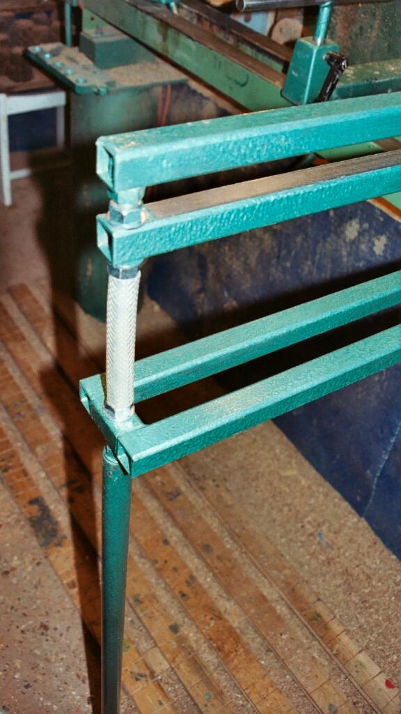 |
Here you can
see the final assembly complete with the Support Leg fitted which is
used to stabalise the Trap when used at the extreme limit of its
adjustment off of the Lathe.
The addition of the Plastic Hose is two fold, firstly it prevents Wood Dust from clogging up the Thread, and also protects your Knuckles. I used short lengths of Garden Hose which allows for some slight adjustment, although recently I did find a Concertina Type Hose in a Auto Shop which would be even better. As explained in part I of this article my preferred position for my System is with the Lathe Headstock off set by 15°, at this point the Trap Assembly was subject to the maximum overhang from the Lathe Bed and if you pushed downward on the end of the Trap the Lathe Bed would Flex. My solution was to make Stabalising Support Leg which would overcome the problem. Set the System up at its extreme overhang and then measure from the bottom of the Lowest Nut to the Floor. This will be the Length of Support Leg you will need but not forgetting to allow for Fitting the Leg and for Adjustment to overcome variations in the Floor Level, if you could see my Workshop Floor you would understand the importance of this. I used a Length of 1" Ø
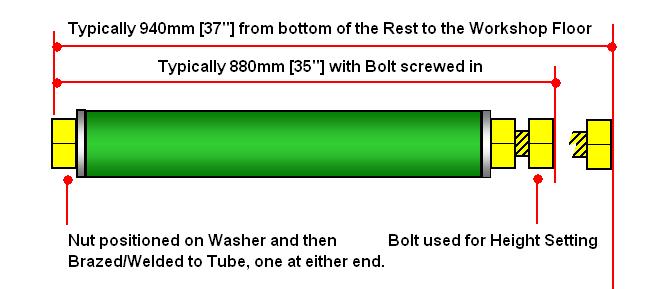
Steel Tube, on each end I Silver Soldered a M12 Nut and Washer one for attaching to
the Trap and the other was for an Adjusting Set Bolt, generally as shown
below, for leveling up when required. |
|
|
The Dimensions in the sketch above are for my set up and therefore are given as "Typical" only, the Set Bolt is screwed right in so that the Leg can be screwed onto the Trap once it is fitted to the Lathe, the Bolt is then screwed out until it reaches the Support Surface i.e. the Floor.
I have a Concrete Floor, but if you have a Suspended or Wooden Floor you may benefit from using a load spreader between the Bolt Head and the Floor this could be either a Steel Plate or even a Hardwood Block, this should be preferably fixed to the Bold Head in some way just to ensure when you inevitably "Kick It" it does not move.
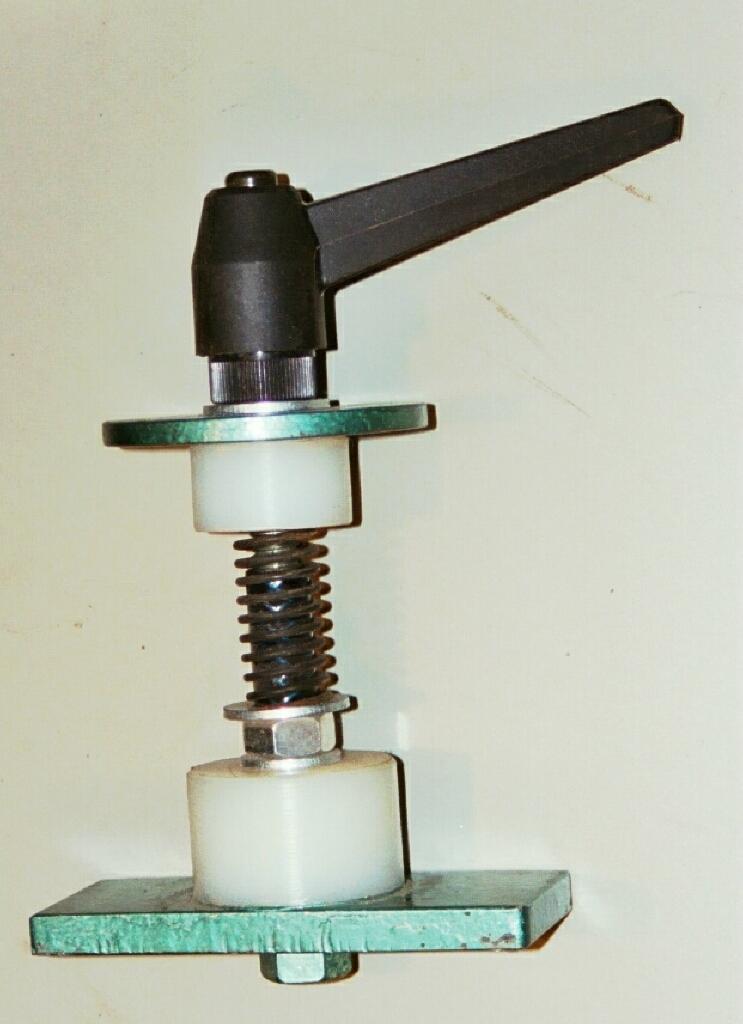
That just leaves the Clamp Mechanism for clamping the Trap Assembly to the Lathe Bed, I used the same principle as the Cross Slide/Banjo for my Lathe, the principle of which is shown in the sketch above and the photo below.
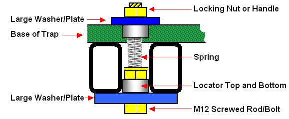
| For the Top and
Bottom Locators I used Nylon Bar this material can be easily Turned,
using Normal Woodturning Tools, the upper one has a diameter to suit the
distance between the Base Bars of the Trap and the lower one has a
diameter suitable for the space between the Lathe Bed [Ways], the Spring
is optional but it does allow you to make any adjustments with ease and
Single Handed.
The bottom Locator and Clamping Plate/Washer are clamped together using M12 Nuts and locked in place with a few drops of Screw Lock, a Washer for the Spring to sit on is also required. The Loosening and Tightening is via the Top Nut, or Machine Handle if used, I found this to be the better option as access to the underside in certain positions can be restricted. |
|
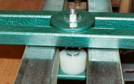
The Clamp Mechanism with M12 Nut as the Tightening method later replaced with the M12 Machine Lever Handle.
![]() Part I of this Article.
Part I of this Article.
![]() Part III of this Article.
Part III of this Article.
|
|
|
LaymarCrafts Woodturning is the Web
Site of Richard & Sheila Stapley Last update 19 July 2007
|
|
Web Site Design & Construction by Richard Stapley. |