My Deep Boring Bar System, Part I covers the Boring Bar with Outrigger, Part II the Trap and associated items. |
| LaymarCrafts Woodturning | Hints & Tips |
| Deep Boring System Pt I |
Like many Hobbyist Woodturners I have over the years collected numerous Tools and Accessories some of which have been more successful than others, the success that had for along time alluded me was making Hollow Vessels, even with all the various aids that are supposed to make it oh so simple.
So when Deep Boring Bars with Out Riggers and Traps started to appear a few years ago they caught my attention, but having already invested in the Stewart, Hamlet, and Exocet Systems plus the odd Special Tool I was reluctant to invest in yet another system that offered no Guarantee of success.
Now I know everyone recommends you Practice and Practice again, but you can waste a lot of money in the process so I thought that if I could take all the systems I already had and make a Boring Bar System that accommodated all these plus one that was adaptable to my Lathe and the available space I had for any Deep Boring Work, then I could perhaps afford to spend some more time practicing.
Their were 4 criteria that I was looking to satisfy:
|
My Deep Boring Bar System, Part I covers the Boring Bar with Outrigger, Part II the Trap and associated items. |
Over the last two years I have refined the design of my System into a working set up that has made Deep Hollow Boring a more successful aspect of my Turning and something I feel relaxed about doing with the knowledge that disasters are few and far between.
The total cost of the System was just under £40 ($55 or €64 for those in Europe) but you will need to shop around for the main body parts as I found that some suppliers were only willing to supply a full random length which is approximately 6m (18ft) whereas other suppliers would supply lengths cut to size. I found Yellow Pages (Not Sure what you have outside of the UK) a good source look under Steel Suppliers also my local Blacksmith (Local Welder of Gates and Fencing Etc.) was a good source for Hollow Steel Tube and the odd bit of Welding.
But do shop around the 1" Square Mild Steel Bar I used for the Main Body of the Boring Bar varied in Price from just under £8, from a company who not only cut it to the exact length I wanted (800mm) but also delivered it to my door, up to £20 from a local Hardware Store. The local Blacksmith supplied the 1" square Hollow Tube cut to length for the Trap and Outrigger (5 pieces in total plus a few off cuts) for £18.
Before you start actually buying material and cutting it to length you must decide exactly what it is you wish to Turn and how much actual space you have available to accommodate the Work piece + the Boring Bar.
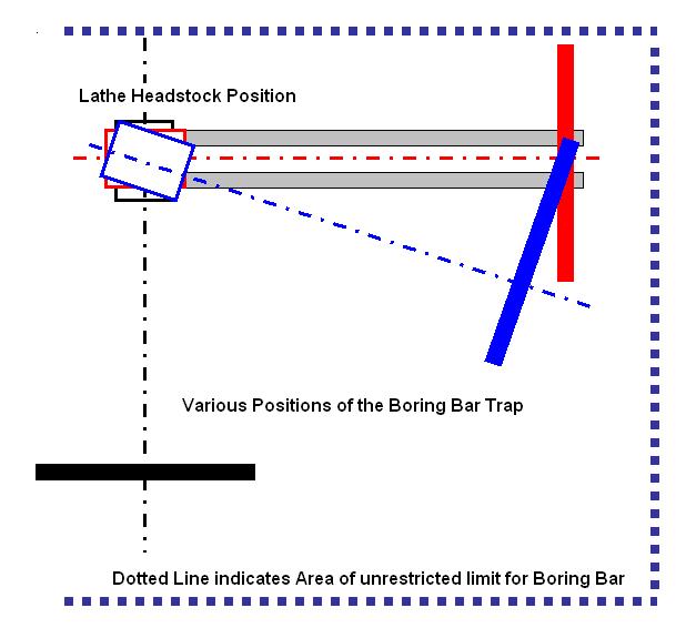
The illustration above shows how I determined the actual length of Boring Bar I could accommodate, the first position would be with the Headstock in its normal position and by then taking a measurement from the point at which the piece which is to be Turned is fixed to the Lathe, i.e. The Face Plate or the Chuck, to the point at which movement of the Boring Bar could "Foul" any item in the Workshop beyond the Tailstock end of the Lathe.
Bearing in mind that to use the system to its maximum in this position you will have to remove the Tailstock, in my case the first or closet obstruction was a Tool Rack and an adjacent Power Point neither of which I wanted to move and I therefore had 1650mm [65"] to play with.
The other two positions indicated are for the Headstock set of centre at approximately 15° which was the maximum I could achieve whilst supporting the "Trap" off of the Lathe Bed, at this point there were no restrictions within the dimension already determined above. With the Headstock at 90° I found I had the same dimension of 1650mm clear into which I could operate.
The diagram below shows how I determined not only the length of Bar I could accommodate but the Depth to which I could Bore into any Hollow Vessel.
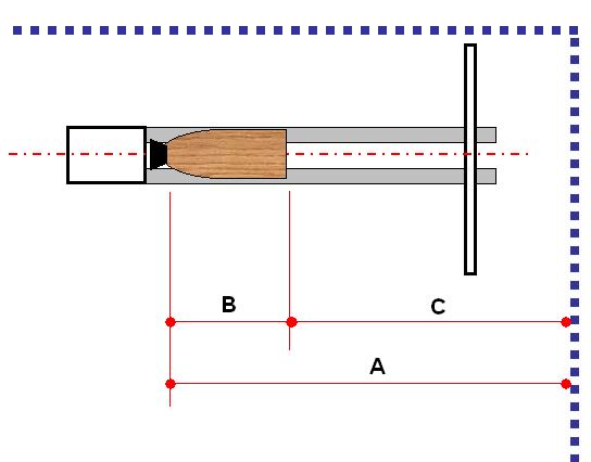
The first question you need to ask yourself is just how deep do you want to Bore, baring in mind that the deeper you go the more substantial the Bar will have to be, my expectations were that I would not expect to go any deeper than 350mm [14"] so in the diagram above "B" is equal to this dimension and with "A" already established at 1650mm, I therefore in theory could accommodate a Boring Bar System with a maximum length of 1300mm or more realistically 1250mm allowing for a good clearance when inserting/extracting the Tool Head from any Closed Form with a restricted opening.
I in fact use the system with the Headstock at the 15° position as this gives a clear access to the Bar under all operating conditions, with no leaning across the Lathe Bed and I also do not need to remove the Tailstock when Turning.
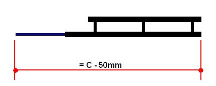 |
With the maximum dimension now determined this needs to be translated into a practical working system. The actual Tool Support Bar will be equal to 1250mm minus the length of the longest Boring Tool you have which in my case was 450mm [actual length - length to be inserted into Tool Bar] which leaves me with a 800mm Bar |
This process is of course purely academic if you have no space restrictions, but you will need to think about the practicality of any system. The Articles that appeared in the Fall 2001 issue of the American Woodturner [ Vol. 16 N° 3] gives plenty of sound advise based on both the Theory Of and the Experiences of Using Trapped Deep Boring Bars and Deep Hollowing Tools, although I do not necessarily agree with all that was written it certainly gets you thinking about the subject.
Having now reached a decision as to the length of the Bar you now need to decide on the actual Bar Size, my requirements were to use 1" Square Bright Mild Steel Bar with a 5/8" Ø Hole for the Tool Holder, this would allow me to use my Hamlet System and by adapting a Stewart Extension Piece I could also use all of my Stewart Tools.
I felt that this size of Bar was adequate for the dimensions and depth of cut I would be attempting to make and so far it has proved to be stable in use with the various Tool Extensions I have.
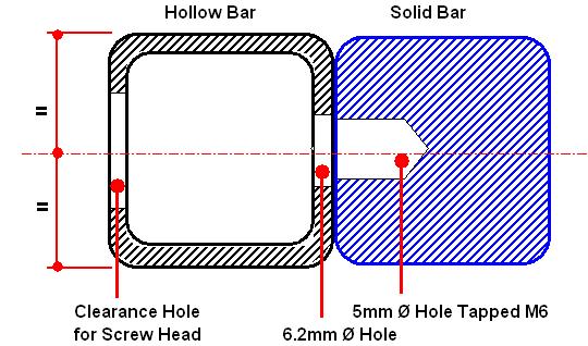
Why you might ask why did I choose to use a Square Bar rather than a Round Bar, which appears to be the norm for this type of tool, the illustration below shows my reason.
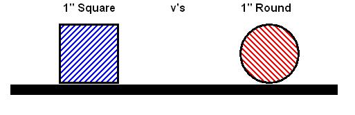
A 1" Square Bar has a greater cross sectional area than the equivalent sized Round Bar [1sq.inch v's 0.786 sq.inch and therefore will be Stronger and less likely to Vibrate, there will also be a larger area in contact with the Tool Rest although this will in theory create more friction you wont have to build up any extra muscles to overcome it I'm sure.
In my experience a Square Bar sitting Flat on the Tool Rest does not create the little indents you can get with a Round Bar when used in such a demanding situation as Deep Boring, therefore the Square Bar will run more smoothly across the support surface.
Finally a Square Bar is easier to work with when making the system, you are working with straight and flat sides to drill into and fix the parts together, which if you construct it, as I did, without any Welding , is a distinct advantage.
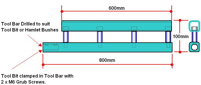
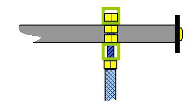
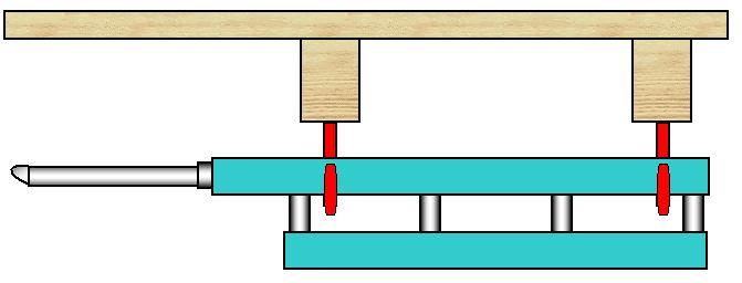
This diagram show the basic principle of my design and the construction of the Boring Bar and its Outrigger.
This form of construction requires no Welding although if you have the means then a Welded construction would be an option.
The Grub Screws used for retaining the Cutter Holder in the Bar are located in the Side of the Bar as in this position they do not so easily fill with Wood Dust.
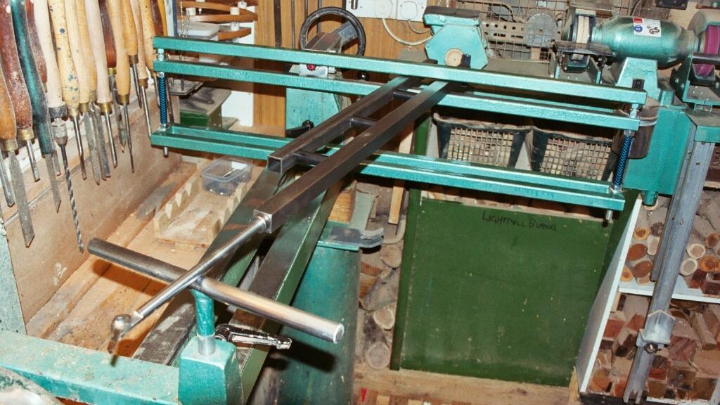
The Photograph at the end of this article clearly shows the Set Up of the System.
I started by taking the 1" square Bright Mild Steel Bar and marked of the centre of each end, in one end I drilled a 16mm [ 5/8"] Ø Hole for the Standard Hamlet Bushes, starting with a Pilot Hole and gradually increasing the size of the Hole until I reached the final diameter.
The Drilling was carried out using my Pillar Drill which "Flexed" a bit when drilling the larger diameter holes and I therefore had to use substantial packing under the Bar and Table to ensure the hole was kept on centre.
The Size and Depth of Hole is up to you but I would suggest that a hole any larger than 16mm in a Bar of this size is the maximum any larger then you should consider a 1¼" or even 1½" Bar.
In the other end I drilled and tapped a hole to suit a M6 Screw this was for fixing the Safety Stop as shown in the Photograph.
To hold the Hamlet Bushes in place I used 2 x M6 Grub Screws [6mm long] with these being located in what would be the inside side of the Bar, this would stop Wood Dust getting into the Grub Screw Socket and therefore ensure the Allen Key was always a good fit.
I then took the 600mm length of 1" square hollow tube and marked it out for 4 equally spaced holes, starting 50mm in from either end, these need to be on the centre line of the Tube and drilled with a pilot drill of 3mm Ø approximately, once drilled make sure that all external burrs are removed.
Clamp the Hollow Tube to the Solid Bar lining up the end with the end into which you have drilled the M6 Hole and the face of the Solid Bar with the Grub Screws in should be in contact with the face of the Hollow Tube with the 3mm Ø Holes drilled in.
Now Drill through each of the Pilot Holes in the Tube and into the Bar for a depth of approximately 10mm using the Tapping Drill for the Cap Head Screws you will be using, in my case I used a 5mm Ø Drill for a M6 Thread. Remove the Bar and Drill out the 4 Holes in the Tube making sure the Hole that was adjacent to the Bar is drilled out to the clearance size for the M6 Cap Head Screw [6.2mm Ø] [or what ever size you choose to use] and then drill out the row of Holes in the opposite side to a diameter just slightly larger than the diameter of the Screw Head.
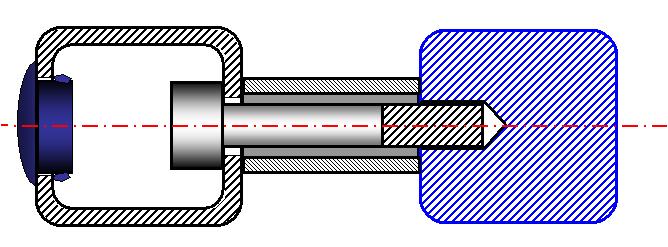
Tap the Holes you have drilled in the Bar to suit the Thread of the Screws you will be using [M6 in my case] and then you will need 4 x 50mm lengths of Tube with at least a 7mm Bore and no more than 20mm outside diameter, I actually used some old Gas Piping which was 15mm OD and 8mm ID. The Tubes/Spacers must be all the same length and the ends as square as possible.
To assemble the Outrigger to the Bar you will require 4 off M6 x 60mm long Cap Head Screws with Allen Key Sockets, thread a screw through the large hole in the Tube, so the Head disappears inside, place the Spacer over the protruding Screw and screw it into the Bar, do not tighten yet, repeat this for all 4 fixings.
Lay the loosely assembled set up on a flat surface and make sure the two Bars are parallel, level and square before finally tightening all the Screws, once tight check again that the assembly is parallel, level and square, loosen and adjust if necessary.
Once you are satisfied that all is in order you can disassemble the Bars and this time add some screw lock to the threads as an extra safe guard. I plugged the 4 large holes that are left with Plastic Blind Grommets and wrapped some heavy duty Insulation Tape around the Spacers to finish the Tool Bar with Outrigger off.
| The final item
is the Safety Stop to prevent the Bar when in use from falling out of
the Trap.
Here I used a short length of Steel Bar held in place with a M6 Pan Head Screw as shown in the sketch. You could also use a large "Penny Washer" or even put a Pin in the Bar protruding either from the Top or the Bottom of the Bar. This is a must, as I found out, because the Trap is behind you and you are concentrating on the Turning it is oh so easy to go that little bit to far, then you do have disaster on your hands. |
|
|
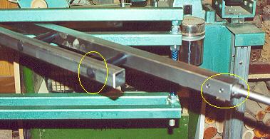
The Plastic Blind Grommets & the Grub Screws for clamping the Hamlet Bush or Tools in the Bar can be clearly seen. |
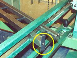
Picture showing the Safety Stop |
When not in use the System hangs on two Cycle Hooks which are both Large and Plastic Coated and are the ideal support.
![]() Part II of this Article.
Part II of this Article.
![]() Part III of this Article.
Part III of this Article.
|
|
|
LaymarCrafts Woodturning is the Web
Site of Richard & Sheila Stapley Last update 19 July 2007
|
|
Web Site Design & Construction by Richard Stapley. |