 |
Picture
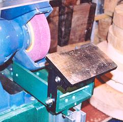
showing the two types of Tool Rest covered here. Materials List for Round Bar Rest:- T-Channel [40
x 20 x 165mm] |
| LaymarCrafts Woodturning | Hints & Tips |
| Grinding Jig Pt I |
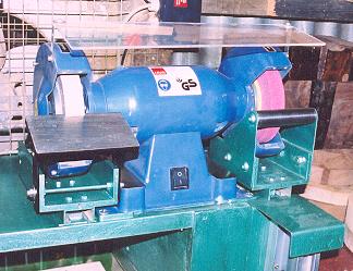
Turning Tools need regular Sharpening and for this you require a means of "Grinding" this can be either a Bench Grinder, or a Wet Grinder these are of course not the only options but they are the two most popular.
Generally the Bench Grinder is the most popular choice because of it's Versatility and Speed of Grinding, by this I mean, generally you switch it on and it's ready for use. It also has the added advantage that you can Grind almost anything with it and cost wise it is generally a Cheaper purchase than a Wet Grind System.
Like the Lathe the Grinder on it's own is a Elementary Machine to get the best out of it you need to Add and Modify the Unit to achieve consistent Sharpening Profile without damaging the Tool you are Sharpening.
The Grinder, although a necessary purchase, often comes so soon after the purchase of the Lathe that Cash is limited and therefore perhaps the Good Deal you go for may not necessarily be the ideal choice in hindsight. Tool Rests are often too flimsy, too small, the incorrect shape or have restricted adjustment, Grinding Wheels are not the latest, must have, "Ruby" or "Blue" type and finally the Spark Guards are inadequate, too small and in the way.
But if you purchase any one of the numerous Jigs and Fixtures on the Market you can easily double or triple the cost of the original Grinder.
Over the next three Hints & Tips sections I will describe the various Modifications and Jigs I have made for my Bench Grinder that now enable me to perform a Good Grind Profile every time and by making this task simple and efficient I find that I now Sharpen the Tools I'm using on a more regular basis and therefore my Turning I believe has improved as a result.
The areas I will cover are:-
The basic requirements for my system is a Bench Grinder, size and shape are not important as the system you make will be suited to your particular Grinder, a sturdy support with clear access below the support platform, the platform supporting my Grinder is a pieces of 1" MDF
Two basic requirements need to be satisfied if you are to follow my design as described, however the possibility to adapt the concept to suit your set up exists, 1] a clear access to the underside of the Grinder mounting Platform as this is where the "Jig Tightening Hand Nuts" will be located and 2] a clearance below the Grinding Wheel Housing, for my set up this is 50mm [2"], you may need to use packing under the Grinder to achieve this or to match the materials you use.
Other areas that you need to be aware of are any Protrusions, Bolts and Nuts etc. on any of the Items do not Foul the Base of the Grinder or the Grinding Wheel Housings when in the normal position, not forgetting that any wear on the Grinding Wheel will require the Tool Rests to be moved further forward on their Slide Guide.
Round Bar Tool Rest
|
Picture
showing the two types of Tool Rest covered here. Materials List for Round Bar Rest:- T-Channel [40
x 20 x 165mm] |
The basis of the design is to provide a simple yet effective system that can be easily constructed and that is flexible in use, I also wanted the two types of Rest to be usable at either end of the Grinder, i.e. to be Interchangeable.
I was also aware that one of the by-products of the Grinding Process are Steel Filings and Grit from the Wheel and that any Grooves or Threads are vulnerable to excessive Wear and Tear if this is allowed to get between mating surfaces, I felt many of the Commercially available systems did not address this situation and therefore Wear and Tear could be a problem within a very short period.
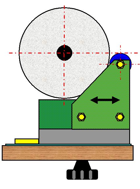
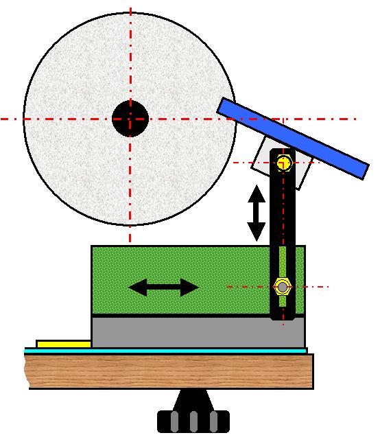
End View of Rest in Position. [Wheel Covers not shown for clarity]
The Principle is a Cradle arrangement which supports a 25mm [1"] Ø Round Steel Bar that acts as the Tool Rest.
The Top of the Bar is level with the Horizontal CL of the Grinder.
Cradle is mounted on a T-Section Channel to form a Slide for adjustment.
To maintain the correct alignment a Nylon Slide Guide is fixed to the Support Platform.
The Slide runs on a 2mm Steel Runner Plate attached to the Platform to reduce the Wear on the MDF Support Platform.
The Cradle is formed from 2 lengths of 50 x50mm [2" x 2"] Angle [Steel or Aluminum], bolted to the T-Section Channel, the side plates are cut from 2mm Steel and bolted to the Angle as shown.
Bolts used to fix Angle to T-Section should have a Pan Head Shape so that they will not foul the T-Bolt when in use and you need to ensure that your design will not foul any part of the Grinder and therefore restricting the Adjustment of the Tool Rest.
Reasonable access to the T-Bolt Hand Nut is required when adjustment is required.
The Materials you use need to be suitable to make a Rigid Structure if the best Grinding results are to be obtained, I used a combination of Steel and Aluminum. The T-Section Channel is of Aluminum and is a common Pipe Support System [Called Hydrozorb here in the UK] and was obtained from a local Refrigeration Wholesaler but similar types are available from Plumbers Merchants or Electrical Wholesalers.
The 50 x 50mm [2"] Angle is also of Aluminum and being 5mm [¼" approx.] thick was ideal, a Steel Angle, which is possibly more readily available would also be suitable here.
The Tool Rest Bar is from 25mm [1"] Ø Mild Steel and was originally an Axle from an old Cart I found at a Junk Yard and sat in my Workshop for many years before I finally found a use for 115mm [4½"] of it.
The Side Supports are cut from 2mm Steel Plate and bolted to the Angles with 2 off M6 Bolts, these plus the Setscrew into the 25mm [1"] Ø Steel Tool Rest Bar gives a sturdy three point fixing. It is important to Profile the Corner where the Bar is located to ensure that the Tool if slid along the Bar does not get snagged by the Support. The Shape is not important but I found the "Triangular" style to my liking.
The Tool Rest runs on a Steel Running Plate which I glued [Contact Adhesive] to the Support Platform for the Slide to run on, I was concerned that the Metal on MDF Contact + the Grit from Grinding, would wear a groove into the MDF and therefore you would loose the accuracy and some stability of the system.
On the Center Line of the Wheel I fixed a Slide Guide Bar, this is the same width as the Open Slot of the T-Section Channel, to ensure that the Tool Rest when being slid in or out is always square to the Grinder Wheel. Made from Nylon [off cuts from the Kitchen Cutting Board used in a previous Tip] it is Screwed to the Support Platform through the Steel Running Plate above.
The T-Bolt is simply an M8 Coach Bolt with a Penny Washer and locking Nut, for Tightening I used a M8 Hand Nut for ease of use but you can use a Lever or just a plain Nut, it is also advisable to have a Large Washer to prevent whatever method you choose from "Digging" in to the underside of the MDF Support Platform.
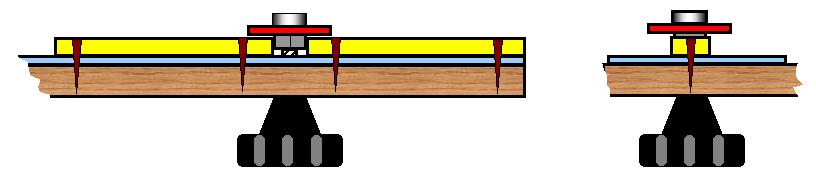
The picture above shows the basic layout of the Slide Guide System and how the Nylon Guide [Yellow] is Screwed to the Platform and through the Steel Running Plate [Pale Blue], it is also worth noting by fitting the Guides right up to the Nut of the T-Bolt assembly you will affectively Trap the Bolt and prevent it from Turning when making adjustments.
Adjustable Platform Tool Rest
All the points listed above will also apply to the Platform Tool Rest the only difference being in the Platform and it's Fixing.
 |
Materials List for
Platform Tool Rest:-
T-Channel [40
x 20 x 165mm] |
In the picture above I have used a Screwed Rod spanning the Cradle which acted as the means of adjusting the Height and also the Vertical Angle, this is no longer the design as I found this restricted the adjustment under certain set ups and it is now replaced by two set screws as shown in the drawings below.
End View of Rest in Position. [Wheel Covers not shown for clarity]
The Principle is a Cradle arrangement which supports Platform Type Tool Rest with adjustment in four planes:
Cradle is mounted on a T-Section Channel to form a Slide for adjustment and to maintain the correct alignment a Slide Guide is fixed to the Support Platform.
The Slide runs on a 2mm Steel Runner Plate attached to the Platform to reduce the Wear on the MDF Support Platform.
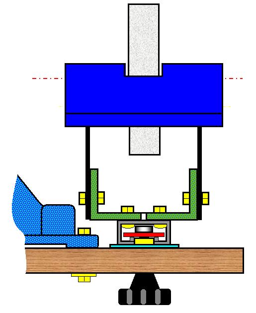
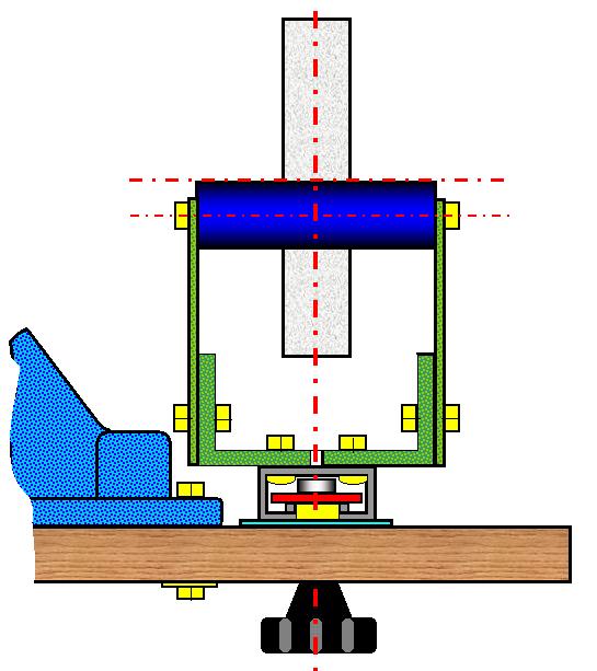
Front View of Rest in Position. [Wheel Covers not shown for clarity]
Bar is fixed to Cradle by drilling and tapping each of the ends for, typically, a M6/M8 Set Screw.
The Cradle is formed from 2 lengths of 50 x50mm [2" x 2"] Angle [Steel or Aluminum], bolted to the T-Section Channel and the side plates are cut from 2mm Steel and bolted to the Angle as shown.
Bolts used to fix Angle to T-Section should have a Pan Head Shape so that they will not foul the T-Bolt when in use and you need to ensure that your design will not foul any part of the Grinder and therefore restricting the Adjustment of the Tool Rest.
Reasonable access to the T-Bolt Hand Nut is required if adjustment is required.
The Materials you use need to be suitable to make a Rigid Structure if the best Grinding results are to be obtained, I used a combination of Steel and Aluminum. The T-Section Channel is of Aluminum and is a common Pipe Support System [Called Hydrozorb here in the UK] and was obtained from a local Refrigeration Wholesaler but similar types are available from Plumbers Merchants or Electrical Wholesalers.
The 50 x 50mm [2"] Angle is also of Aluminum and being 5mm [¼" approx.] thick was ideal, a Steel Angle, which is possibly more readily available would also be suitable here.
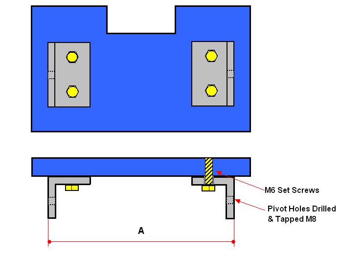
The Platform is made from a piece of Steel Plate, 75 x 125mm x 9mm, to which I have screwed two pieces of Steel Angle [25mm x 25mm x 37mm] using M6 Set Screws these pass right through the Platform and were then filed flush with the top surface of the Platform.
The Angles form the Platform Pivot Mechanism and each has a M8 Tapped Hole centrally placed, by using a Tapped Hole the adjustment can be achieved using one Spanner or Allen Key if you use a Bolt and Nut then adjustment requires the use of two Spanners or an Allen Key and Spanner which although is acceptable you may find adjustment slightly awkward.
Dimension "A" is equal to the outside width of the Support Cradle and it is important that the Angles are both parallel and square to the Cradle if Grinding Accuracy is to be achieved.
Into the Platform I cut a recess to straddle the Grinding Wheel, this gives you a more flexible Grinding facility and better control. I rough cut this recess [Drill, Saw and Chisel] and then used an old Grinding Wheel on the Grinder to finish off the Rough Edges allowing a 3mm gap either side of the Wheel for clearance. see sketch below.
The Vertical support arms enable both Vertical and Angle Adjustment via the Slot, in my case the old supports from the Grinders original Rests were used and this saved a lot of work, if you are not so fortunate then you need some Steel Plate at least 3mm thick with a Slot in one end of approximately 6.5mm wide [if using M6 Bolts] and 25/40mm long depending on your Grinder and the size of wheel.
The Tool Rest runs on a Steel Running Plate which I glued [Contact Adhesive] to the Support Platform for the Slide to run on, I was concerned that the Metal on MDF Contact + the Grit from Grinding, would wear a groove into the MDF and therefore you would loose the accuracy and some stability of the system.
On the Center Line of the Wheel I fixed a Slide Guide Bar, this is the same width as the Open Slot of the T-Section Channel, to ensure that the Tool Rest when being slid in or out is always square to the Grinder Wheel. Made from a Plastic [off cuts from the Kitchen Cutting Board used in a previous Tip] it is Screwed to the Support Platform through the Steel Running Plate above.
The T-Bolt is simply an M8 Coach Bolt with a Penny Washer and locking Nut, for Tightening I used a M8 Hand Nut for ease of use but you can use a Lever or just a plain Nut, it is also advisable to have a Large Washer to prevent whatever method you choose from "Digging" in to the underside of the MDF Support Platform.
If made correctly and to identical dimensions the Cradles should be fully interchangeable so that you have a choice of Bar or Platform for both Wheels.
Some of you have indicated that you have had difficulty finding the Aluminum Channel as used above, I understand that two Steel variants, Unirail and Unistrut are more readily available and these have been used successfully by some of you who have made these Jigs.
![]() Part II of the Grinding Jig Article.
Part II of the Grinding Jig Article.
|
|
|
LaymarCrafts Woodturning is the Web
Site of Richard & Sheila Stapley Last update 19 July 2007
|
|
Web Site Design & Construction by Richard Stapley. |