| LaymarCrafts Woodturning | Hints & Tips |
| Safety Switch for the Lathe |
I believe every Lathe should have a Remote Safety Switch / Panic Button, most of us consider only a Foot Operated Switch and in fact this is generally all that is commercially available. However over the years I have discovered that a Foot Switch is not ideal for many situations.
With one of those precarious incidents fresh in my mind and with the resulting bruise still clearly visible I set about finding a more Flexible solution to ensure my future well-being and therefore many happy hours of Turning.
Anybody who turns Hollow Vessels will tell of the dangers and high on this list will be the time when it becomes impossible to remove the Tool from the piece because the shavings have cut off the exit from the Vessel. You now find two hands are required to hold onto the Tool and you are not only meter plus away from the Stop Button but without a Hand available to use it.
The answer therefore has to be a Switch that does not always need the Hand to operate it, we have a number of options, the Foot, an Elbow or the Hip, in fact any part of the Body you wish to choose, with this solution you can use any one of these to Stop the Lathe.
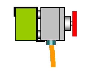
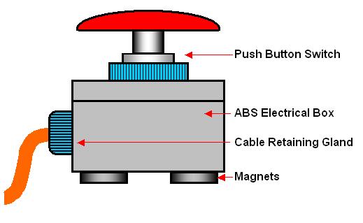
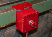
This is the basic Switch it comprises of a Push to Break industrial Switch with a Mushroom Head, although this is the my preference any form of Micro Switch (Push to Break) could also be used with a suitably sized Push Button providing it is robust enough for the job in question.
The Switch is mounted in a Heavy Duty ABS Type Terminal Box with a trailing lead for the Power Supply, this ideally should be, as a minimum, a Double Insulated Cable and preferably a Flexible Armored Cable as it will carry 240v (110v in the USA) and trails around the Workshop when in use.
I have fixed (Super Glue) 3 Magnets to the bottom of the Box and as you will see this gives the idea its Flexibility or Roving capability.
The Switch Box is connected via it's Power Lead to a Wall mounted Control Box that has a 240v Power Supply from a RCD Unit on the main Distribution Board in the Workshop, a Power Switching Contactor (4-Pole 16amp Contactor) and a Standard 3-Pin Socket Outlet, for the Lathe to be plugged into, as per the Wiring Diagram below.
When using Metal components such as the Switch Box you must ensure that all the metallic parts are adequately Earthed in accordance with the Regulations in force in your Area.
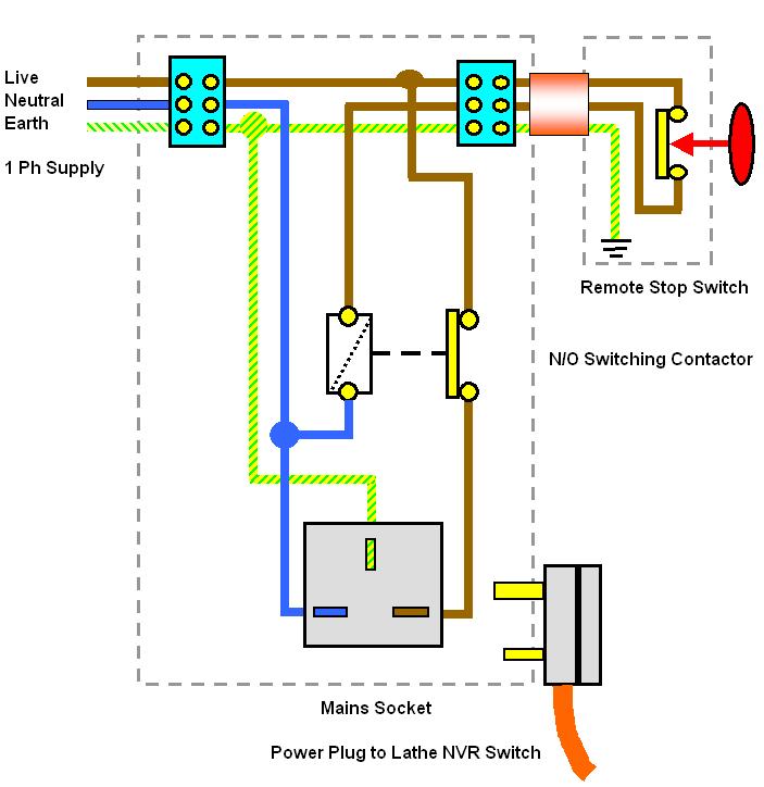
Most Switches would not be capable of Safely Switching the Current of a 1HP (0.75kW) or larger Motor and it is therefore important that you incorporate a suitably rated Contactor as shown above.
Consult the Motor Plate for the Motor Rating and Running Current of the Motor on your Lathe or if you intend to use any other Power Tools then their Motors also and design the system to accommodate the Motor with the Highest Rating.
The principle of operation is that with the Lathe (or any other m/c with a No Volt Release [NVR] Switch) plugged into the Standard Socket, Power is available to the On/Off Switch on the machine and will function as normal. When the Stop Button Switch is depressed the Coil of the Contactor is de-energized and the N/O Contact will Break and drop the Live Supply, via the Power Socket, to the No Volt Release Switch on the Machine.
If you do not have a Push to Break Switch then the alternative is a Push to Make Switch and therefore you will need to Wire through a N/C Contact and not a N/O Contact on the Contactor, otherwise all wiring is as shown above.
It is worth mentioning here that this devise will only permanently stop a Machine with a NVR Switch and only stop a Machine with a Simple On / Off Switch with the Button held in by hand or foot.
The first set up is with the Switch Module contained in a Foot Switch. This comprises of a Plywood Base which has on the underside a Rubber Mat as an anti-slip precaution and on the top I have glued (Contact Adhesive) a sheet of thin Steel, this is so the Magnets on the Box can do their job.
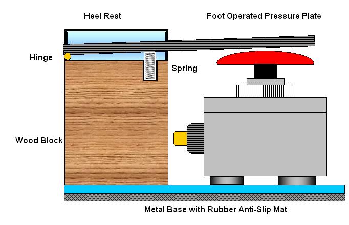
At one end we have a Hardwood block to which you screw the base described above. The height of this block is important and needs to be the same height as the Switch Box + the Magnets + the amount the Button Switch protrudes beyond the Box when the Contacts are Broken (i.e. the Switch is Off).
Too this block you need to fix,
using a hinge, another piece of Plywood again with a Rubber Mat glued to the top
of it as an anti-slip precaution. Below this "PEDAL" you also need a
Spring so that it will always return so allowing the Button Switch to Make (i.e.
the Switch is Made). I simply drilled a hole in the block into which I popped a
suitable Spring ( mine was from an old pair of Garden Shears).
Finally you need to make a Heel Rest for you to rest the Heel of your Foot on.
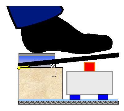
With the Switch in place you can now position the unit on the Floor in front of where you are working with Heel of your Foot (Shoe/Boot) on the rest all you need to do to operate the Switch and therefore turn off the Lathe is to let the Foot fall onto the "PEDAL" which will make contact with the Button Switch and so Break the Power supply to the Contactor.
In use this Switch has never
let me down and providing that it is always placed on a firm surface (never on
top of the pile of shavings around your Lathe) and is kept clear of any debris
there is no reason for it not too.
|
|
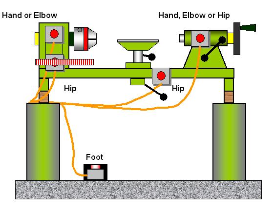
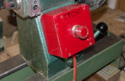
The Unit out of it's Foot Holder can be used anywhere on the Lathe and illustrated above are just some of the locations where it is possible to attach it.
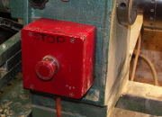
On the Headstock at a high level it can act as a Panic Button or an Elbow Button, when placed lower down I find it is ideal to switch using your Hip when parting off and you have the Parting Tool in one Hand and the Precious Item you are about separate from the Lathe in the other.
Attached to the Tailstock it becomes ideally positioned for Hand or Elbow when Drilling or Boring. If any of the surfaces you wish to use are not really suitable, for instance my Tailstock is of Aluminum and the Headstock had the Makers Name Cast onto it, then the addition of a suitably sized Steel Plate either Glued or Screwed in place will overcome this problem.
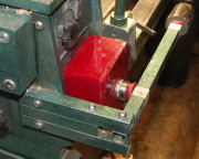
On the Bed Bars is also another
Hip operating position and I use this when Hollow Turning or Sanding. When used
on the Bed Bars I found that I some times inadvertently could knock it off the
Lathe onto the Floor, so I made a simple Cradle to hold it more secure, this was
made from a piece of thin Steel bent to fit over the Bed Bar with a Lip at the
bottom to act as a "Stop", in this Cradle the Switch can easily slide
along the Lathe to the most suitable position.
|
|
Because this unit in effect controls a Power Socket any Machine Plugged into it will operate with this System and I use it on the Bandsaw and Pillar Drill, both of which are fitted with NVR Switches, using the Foot Switch and with my Hand Router and Jigsaw (Both via a NVR Extension Lead I have also made) again using the Foot Switch.
 |
 |
 |
 |
| Headstock End | Headstock End Hip Lever | Lathe Bed | Tailstock End |
Go to Tip #60 for details of
the additional
Hip Lever attachment for the above Switch as shown in the picture ![]()
A word of Warning this Control Module Project requires a reasonable understanding of Electric's and you must adhere to all Applicable Local and National Standards and Codes of Practice. You should not attempt this if you have any doubts or reservations as to your competence to do a Safe Job.
If in doubt use the services of a Competent and Accredited Electrician to advise and help with this project.
If in Doubt ASK.
Reversing the Direction of Rotation for a Single Phase Late Motor
A valuable asset with any Lathe [and also some other Machines] is to have the capability for Reversing the direction of rotation, this is particularly useful for achieving a Fine Finish. Running any Single Phase Motor in reverse is possible and will not have any adverse or damaging consequences to either the Motor or the Lathe.
However there are some points to bear in mind if you intend to have this facility on your Lathe or any other suitable Machine:-
1) There are numerous types of Single Phase Motors in use and although the principle is the same for all the following Wiring Diagrams may require some modification.
2) Rotation Switching should be activated via a suitable Change Over Switch correctly rated for the Motor and with a central Neutral or Off Position.
3) The Motor must be at a standstill [Stopped] before switching from Normal Rotation to the Reverse Rotation Position.
4) With the Lathe Spindle running in reverse (Clockwise Direction) there will be tendency for any Chuck, Face Plate or Item Screwed onto the Lathe Spindle to unscrew and precautions must be taken to ensure that this cannot occur. If not attended to this is an Accident waiting to happen.
5) Finally apply the rule of checking, just like marking out and measuring dimensions in Woodturning and Woodwork, measure and then measure again, only in this instance check the wiring then check again, once you cut the Wire their may be no going back.
The diagrams below show the Wiring for Standard Rotation (fig.1) and for Reverse Rotation (fig.2) in all cases, regardless of the Motor type, the principle of reversing is the same, fig.3 shows the Wiring with the Reversing Switch in position.
You will require a Switch to change over the wires to the Start Winding of the Motor, terminals/wires Z1 and Z2 in the diagrams, these may also be colour coded as Yellow and Blue, but with so many Imported Motors now in use these wire Colours and terminal designations cannot be guaranteed.
Remember the Reversing Switch must be Rated no lower than the Maximum Rating of the Motor which you will find on the Motor Plate, typically this will be 5.1 Amps for a 0.75kW [1HP] 230V/1Ph/50Hz Motor, in my case I used a Switch Rated @ 10Amp.
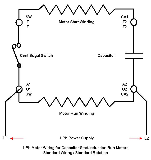
Fig.1
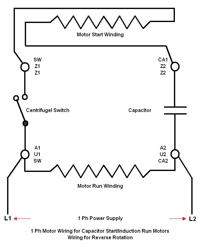
fig.2
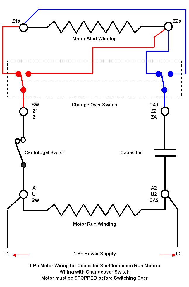
Fig.3
A word of Warning this Modification requires a reasonable understanding of Electric's and you must adhere to all Applicable Local and National Standards and Codes of Practice. You should not attempt this if you have any doubts or reservations as to your competence to do a Safe Job.
If in doubt use the services of a Competent and Accredited Electrician to advise and help with this project, your local Motor Rewind Company could be your best source of advise and may well do the work for you.
If in Doubt ASK.
|
|
|
LaymarCrafts Woodturning is the Web
Site of Richard & Sheila Stapley Last update 19 July 2007
|
|
Web Site Design & Construction by Richard Stapley. |