| LaymarCrafts Woodturning | Hints & Tips |
| Drilling Depth Gauge for the Tailstock |
This article details the modification that I made to the Tailstock of my Lathe enabling me to accurately and consistently gauge and control the Drilling Depth of any drilling operation whether using Twist Drills, Brad Point Drills, Spade Cutters or Forstner Bits.
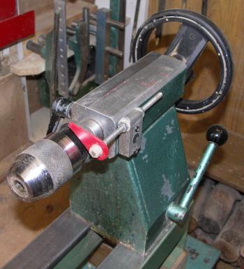
In the picture above you can see the Depth Gauge in use and also the "Handy Rule" Tip which was covered in a previous Hints & Tips and the Steel Plate stuck to the side of the Tailstock which holds my Magnatised Roving Emergency Stop Switch which will be the subject of a future Hints & Tips.
If this looks familiar then perhaps you saw my original article that appeared in the Hints & Tips section of " Woodturning" and also appears in the 1999 edition of "Further Useful Tips for Woodturners".
Most Lathes that I have come across do not have any means of indicating or measuring the Drilling Depth for a Hole, and most Turners will resort to various combinations of Tape, Pencil Marks or Stops these generally can be all right for one offs, but if a accurate and repetitive depth is required then a simple and affective method of gauging depth has to be available.
My design was instigated by the need to produce a batch of 100 Keyrings which required a 8 mm Hole Drilled to a depth of 20 mm, the accuracy of depth was an essential part of the Keyring design if it was to work properly and look attractive.
Having drawn the basic concept for the Depth Gauge I then sorted out items I could use from a large trunk of odds and ends I have accumulated over the years (old washing m/c parts, scraps of metal, off cuts and plastic etc. etc.) this meant changing the original design to match the available materials, and your design may well have to be adapted to match the materials you have available.
My Lathe is the Hegner HD200E and this has a square shaped Tailstock which makes fixing of my design very easy, however if the Tailstock of your Lathe is not square then an adapter can be made using a short length of Channel Section to bridge the curvature of the Tailstock Body.

The Channel may need shaping to fit the exact contours of the Body so therefore it is better to use Aluminum Channel as this is easily worked. You can either fix the Channel as a separate item or use it as a spacer between the Depth Gauge Block and the Tailstock Body as shown on the right above.
I chose to locate the Depth Gauge on the side of the Tailstock facing me, the opposite side would have been my preference but this is where the Locking Lever for the Tailstock Barrel is located, alternatively it could have been located on the top of the Tailstock.
As the main body was intended
to be a permanent fixture it is important that it does not interfere with or
obstruct when not in use and when turning between centers.
 |
The main body was made from a
small block of Aluminum, which was fixed by two screws onto the Tailstock. I
first found the centre line of the Tailstock barrel and marked this on the side
of the Tailstock where I would be fitting the block, I then drilled two fixing
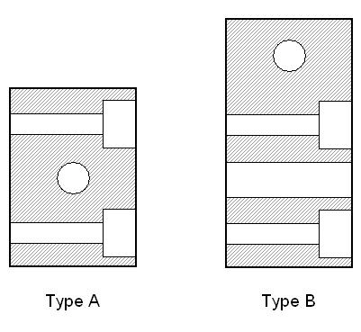
holes through the block either side of it's centre line. Two "Blocks" are shown here type "A" is the ideal design, but type "B" has an additional Hole because on the Hegner Tailstock there is a "Anti-Rotation" Grub Screw in the Tailstock, this prevents the Barrel from rotating. The two Fixing Holes are shown here Counter Bored they can be Left Flush of Countersunk to suit the Screws used. No dimensions are given as each Lathe will require it's own Size and Shape. In my particular case the Block (B) I used was 50mm x 25mm x 12.5mm. Although I used a Block of Aluminum a piece of Angle would be suitable as an alternative. |
These holes were 3.5 mm diameter and can be either counter bored, countersunk, or left flush to take the M3 Screws, you choose to use that would fix the block to the Tailstock. With the block held in place I marked the position of these holes onto the Tailstock and then drilled and tapped them to suit the M3 Screws. It is important that these holes are not so deep, that you drill into the Tailstock Barrel, so Measure and then Drill these holes very carefully.
You now need to drill a hole in the block to take the depth gauge, this is drilled on the centre line (between and at 90° to the previous fixing holes for type "A") as I was using a M6 Screwed Rod the hole size I used was 6.5mm diameter clearance hole to allow for easy adjustment when in use.
The block is now ready to be fixed in place on the Tailstock, once this is done you can then determine the required length of adjustment for the Depth Gauge Adjustment Rod which is made from a length M6 Screwed Rod.
To determine the length of Screwed Rod required you first measure the maximum travel of the Tailstock Barrel, then add the width (through which the rod will pass) of the block previously fitted to the Tailstock, plus the thickness of the M6 Nuts and Washers used (4 off) and finally the thickness of the Pointer.
For my Lathe this equated to 135 mm (actual Barrel travel is 80 mm), it is important that the Screwed Rod is no shorter than the calculated length and within reason can be longer if thought necessary.
I now cut the M6 Screwed Rod to
a length of 135mm and then cleaned up the cut ends to remove any burrs and
to ensure the M6 Nuts run freely up and down the Rod.
q
 |
You
now need to make some form of Pointer to act as the reference indicator
for the Depth Gauge.
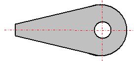
I used the Plastic Lid from an Ice Cream Container as this is quite thick and yet is flexible and should therefore not break if snagged, the general shape is as shown above. This can be Cut quite easily using a Stanley Knife and the 6mm Hole Drilled or even Punched out. |
It is now time to assemble the Depth Gauge Rod and Pointer, first place a M6 Nut on one end of the rod and screw it down a couple of cm's, add a Washer then the Pointer and another Washer and finally another M6 Nut. Tighten up the whole assembly, clamping the pointer between the Nuts and Washers, ensure the end of the Screwed Rod is flush with the last Nut you put on and then tighten the first Nut. For additional security I added a drop of Super Glue to the thread around each of the Nuts.
Now place another M6 Nut onto the other end of the Screwed Rod followed by a Washer, this should be Screwed on almost up to the pointer end. Thread the assembly through the 6.5mm hole in the block fixed to the Tailstock (from left to right) so the pointer is at the Barrel end of the Tailstock and add the final Washer and Nut. (see below)

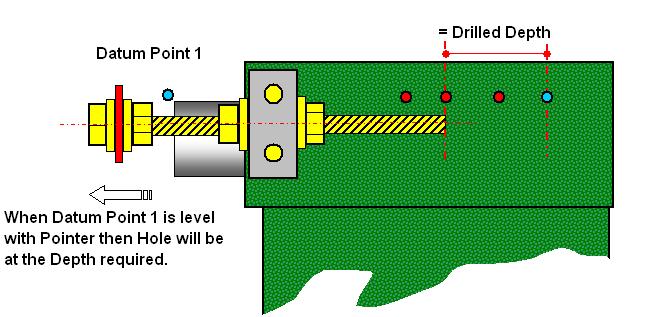
We now need to fix the Datum Points from which all future measurements will be made, for Datum 1 I used the end of the Tailstock Barrel and therefore I adjusted the Depth Gauge Pointer to align with the End of the Barrel (with the Barrel fully retracted into the Tailstock) and clamped it in place in the holding block.
The other end of the Screwed Rod now becomes Datum Point 2 or Zero Depth, this point needs to be accurately marked either by etching a mark with something like a Hacksaw or by painting a line. Alternatively you can fix a graduated scale (or a rule) which should read from right (0 mm) to left (80 mm) i.e. equal to the maximum travel of the Tailstock Barrel.
In use you set the plain end (RH End) of the Screwed Rod, at the correct distance equal to the drilling depth* you wish to achieve, from the Datum Point 2.
Do not forget to allow for any Brad Point or Angle of Drill Tip when setting this distance.
In use the Tailstock Barrel is fully retracted (important as this is the Datum Point) and the Depth Gauge set to the required Drilling depth, the Tailstock is then moved forward on the Lathe Bed until the Drill Point is just in contact with the item to be drilled, and locked in place.
With the Lathe Running the Tailstock Barrel is wound forward and Drilling will commence, you continue to Drill as normal until the End of the Tailstock Barrel (Datum Point 1) reaches the Pointer of the Gauge. The resulting Hole will now be to the required depth as will all subsequent Holes with the same settings.
As the maximum travel for my Tailstock is 80mm I can only Drill Holes to this Depth without making a second setting for the Depth Gauge or halving the final Depth required, i.e. for a Depth of say 100mm then I would set the Depth to 50mm and proceed as above, then retract the Drill from the Hole by winding in the Tailstock Barrel. Then with the Lathe Running gently push the Tailstock forward so that the Drill enters the Hole, when you feel the Drill make contact with the bottom of the Hole you lock the Tailstock in position and Drill another 50mm using the Depth Gauge as your guide.
As I make a number of items that require a certain depth of hole I marked these depths onto the Tailstock Body using a Hacksaw to scribe a line at the relevant depth, now when ever I make any one of these items I can very quickly set the Depth Gauge to suit. Remember though to make a note of which mark is for which item, I drew a sketch of each position and noted the relevant details and had this Laminated. It is now fixed to the wall near to the Tailstock.
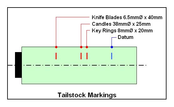
Laminated Sheet fixed to the
Wall near to the Tailstock for quick reference.
Magnet
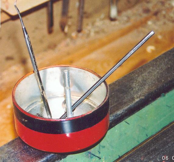
My fourth Magnet Tip is ideal for attaching to the Lathe Bed or Head Stock Cover when dismantling or undoing any item where small parts are involved. The container will hold such things as, Screws, Button Jaw Components, Grub Screws as well as Allen Keys and Spanners etc. etc. and prevents these items from getting lost, when changing or setting up, in the Wood Shavings around the Lathe.
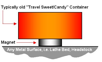
This idea is not new, in fact a proprietary version is available at most Tool Stores, the benefit is that it is made from readily available items and therefore at very little cost and the shape is more versatile for our requirements than those that I have seen in Shops.
The Container used was a Tin approximately 80mm Ø x 30mm deep which originally contained Fruit Flavored Travel Sweets (Candy), alternatively you can use the Tin that your Wax Paste comes in, or a Tobacco Tin or even a Plastic Container.
Simply attach a Magnet (an Old Speaker Magnet is ideal) to the bottom of the Container using a suitable Adhesive, give it a coat of paint and you have the ideal Magnatised Holder.
Another use for this item, or even a second one, providing the Shape and Material are compatible is as a holder for Jars or Bottles of Finishes (Sanding Sealer, Melamine or Friction Polish) or Bottles of Dye, Super Glue etc. etc. rather than just standing them on the Lathe Bed or Headstock where they can easily get knocked over.
Storage is simple, just fix a
small piece of Metal Sheet to the Wall in a convenient place and the Container will
be held ready for use.
|
|
|
LaymarCrafts Woodturning is the Web
Site of Richard & Sheila Stapley Last update 19 July 2007
|
|
Web Site Design & Construction by Richard Stapley. |