| LaymarCrafts
Woodturning |
Hints
& Tips |
Although I already had a
Ball Cutting Jig with my Multi-Function Baseboard System I had the need for a more
compact and an easier to set up Ball Cutting Jig for the making of one
off's.
There were a number of
designs available on various Woodturning and Metal Turning Sites and I used some
of the features from some of these, whilst utilising available materials
and more importantly my limitations in Machining Facilities.
Apart from the necessary
Hand Tools, I am limited to a Pillar Drill, whereas a more sophisticated unit
could definitely be made with the aid of a Milling Machine and Metal Lathe.
Most modern Lathes have a
relatively large swing over the Bed, in my case I could if I really wanted to
Turn a Ball up to 400mm diameter [nearly 16"] in reality I only was looking
to Turn Balls of 100/125mm diameter [4/5"] and as any Jig will have a High
Centre of Gravity the lower you make the Jig then lighter materials of
construction can be used whist maintaining stability.
My final design actually
gave me the potential to Turn a Ball of 180mm diameter [7"] and I could
have added another layer of the 20mm MDF to the base and still had the
capability for a 160mm diameter Ball [6"+], of course if your requirement
is for a larger capacity then you will need to adjust the dimensions
accordingly.
 |
The
main component parts of the jig are:-
Tool Post from
25mm x 25mm [1" x 1"] Square MS Bar with a 10mm Ø HSS Round
Nosed Cutter.
Tool Post Support
Spigot from 12.5mm Ø Silver Steel Bar, this allows for height adjustment
for various Tool Types and Tool re-grinding.
Tool Post is
locked by two M6 Grub Screws locating on a flat ground onto the Spigot.
Main Bar has
Support Spigot fixed, again by 2 x M6 Grub Screws + an Optional Spot Weld.
The Main Bar also
has 7 x 6.5mm
Holes at a pitch of 10mm for the Swivel Bolt [M6] this allows Radius
Adjustment of Cutter and therefore will determine diameter of the Ball.
The Support base is
constructed from 20mm thk. MDF with a central M12 Screwed
Rod. which has a dual roll for both the Pivot Screw and Locking.
Laminated MDF construction Glued and Screwed, Top has a piece of Formica for smooth
running of the Jig in use.
M12 Screwed Rod
is drilled and tapped M6 in one end to take the Jig Swivel Bolt
whilst at the other end locking in place is via a
Black Plastic Knob or any suitable alternative, Lever, Nut etc.
The Base Board/Table is
constructed from 20mm thick [because that is what I had to hand] MDF, the top
piece is 220mm long by 185mm deep [8½" x 7¼"] and this is off set
from centre with the overhang at the front.
|
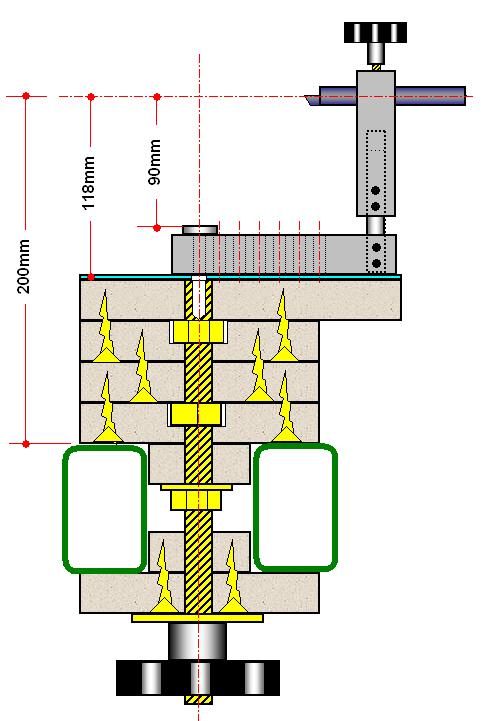
The dimensions for the
top piece is based on the swing dimension of the Main Bar taken from the centre
of the First Pivot Hole to the opposite end of the Bar [110mm or 4¼"] this
will equal the width of the Top and using the same distance plus half the width
over the Lathe Bed [Ways] for the front to back dimension i.e. 150mm ÷ 2 = 75mm
[3"] + 110mm = 185mm.
If the Lathe Bed [Ways]
are 150mm [6"] wide then it must follow that the Centre Line of the
Headstock will be 75mm [3"] from the front or rear of the Lathe Bed.
You will have to make the
dimensions to suit your particular Lathe by increasing or decreasing the
dimensions accordingly.
The 3 off pieces of MDF
which make up the Block below the Table are cut the same length i.e. 220mm and
the width equal to the width over the Lathe Bed [150mm]
A fourth piece is cut to
the same dimensions for the Clamping Plate, you also need two pieces, again
220mm long and this time they need to be equal to the inside dimension of the
Lathe Bed, in my case 50mm [2"] this dimension is critical as any slackness
here and you will find it difficult to Centre the Jig and therefore make a
perfect Ball.
The fit should be any
easy fit but without any lateral play, the base piece is less critical so make
the top one first and if it is to sloppy use it on the bottom and try again with
the second piece.
Now you need to drill the
hole for the M12 [½"] Screwed Rod which forms the Pivot Point and the
Locking Bolt, the holes are central left to right and in from the back edge by
75mm [or half the distance over the Lathe Bed], the hole needs to be a close fit
and therefore a 12mm hole is best.
In two of the lower
pieces you also need to recess the holes to accommodate the M12 Nuts which aid
the alignment of the Screwed Rod in the assembly and the accuracy of maintaining
central alignment.
The M12 Screwed Rod
requires to be Drilled and Tapped in one end to take the M6 Pivot Bolt.
You now start the
assembly by Gluing and Screwing the MDF Pieces together as shown in the sketch
above, using a Set Square to check that the Screwed Rod is 90° in all
directions, check after each layer is added and adjust if necessary.
For the Bottom Block or
Clamping Plate you Glue and Screw the two pieces together and when set open up
the 12mm Hole to say 13mm so that it slides easily on or off the Screwed Rod, I
also fixed a metal plate around the Hole to protect the MDF from the rigors put
on it by the Clamping Nut.
When the main block is
set and cleaned up you can add a piece of Formica to the top as this will give
you a smoother and harder wearing surface for the Jig itself to Pivot on, do not
forget to drill a hole for the Pivot Bolt before you Glue it in place, this will
also act as a reference point when carrying out the final Gluing and Positioning.
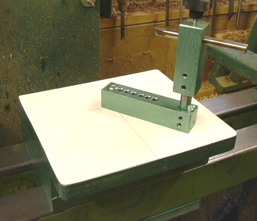
The Tool Holder/Swivel
Bar as photographed above was constructed using some of the left over 25mm [1"] Square Bar from
my Deep Hollowing Bar project.
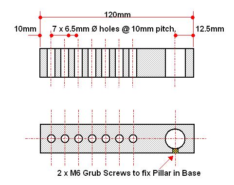 |
The
Horizontal or Swivel Bar/Base is from a 120mm [4¾"] length of the
25mm Square Bar and is drilled as shown in the sketch.
The important
factor here is accuracy as any holes out of true or square will be
amplified at the Cutter Tip.
As I was using an
M6 Bolt as my Swivel Point the series of 7 holes, to give me adjustment
according to the size of Ball I would be cutting, I drilled them to
6.5mm to limit the amount of play,
Again the hole
for locating the Pillar was determined by the diameter of the Pillar I
was using, i.e. 13mm hole for the 12.5mm Pillar.
The Pillar is
locked in place via 2 M6 Grub Screws.
|
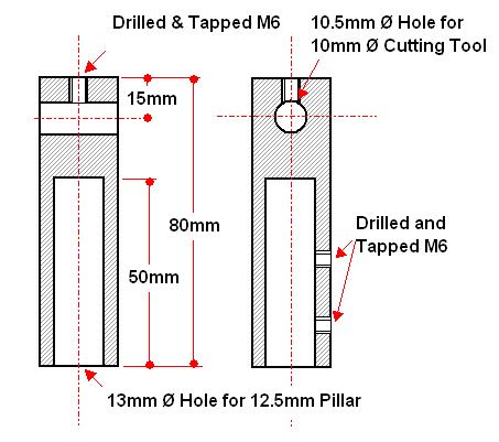
For the
Vertical Bar / Tool Post I again used a 80mm [3¼"] length of the
25mm Square Bar.
The actual
dimensions for both pieces will be determined by the materials you use
and the Lathe you have.
The hole for the
Pillar was drilled with the Bar in my Lathe Chuck [I have the Axminster
with the standard Engineers Jaws] and the 13mm Drill held in the Jacobs
Chuck in the Tailstock.
For the 10mm Ø
Tool Bit I drilled a 10.5mm Ø hole and in the top of the Post I drilled
and tapped an M6 hole for the Tool Locking Screw.
To fix and provide a means of adjusting
the Tool Post height, I used 2 x M6 Grub Screws, which clamp onto a Flat
that is ground onto the Pillar, this can be seen in the Photo
above.
|
 |
|
LaymarCrafts Woodturning is the Web
Site of Richard & Sheila Stapley
All Content, Articles, Pictures & Diagrams as Presented are the ©
Copyright of LaymarCrafts & Richard Stapley
Last update 06 May 2008
All Rights Reserved |
|
Web Site Design & Construction by
Richard Stapley. |