| LaymarCrafts Woodturning | Hints & Tips |
| Multi Function Baseboard, Sled and Carriers Pt. II |
In Part II of this article I describe three Holders, with four uses, that I have developed for use with the Sled described in Part I, these are the Dremel Holder, A Ball Cutting Jig and A Drill Guide.
The Dremel Holder
The Dremel or anyone of the numerous Mini Power Tools can be supported and therefore used with the Sled for Decoration or other Embellishment of Turned Items, and is perhaps the easiest to accommodate.
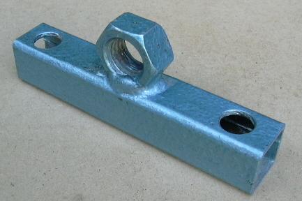
The thread on the Dremel, onto which the Plastic Cover is screwed is, in the UK, a M20 Thread and therefore all that is required is an M20 Nut.
|
|
A length of the 25 x 25 [1" sq] Box Section 132mm [5¼] long with two 14mm Holes Drilled to match the position of the front end Screwed Rods of the Sled. The Nut is carefully positioned, make sure the Nut is not too far forward or the Body of the Dremel will foul the Box Section Cross Support and access to the Locking Pin will be restricted, and then Welded in place The adjustment is via the Locking Nuts either side of the Cross Support.
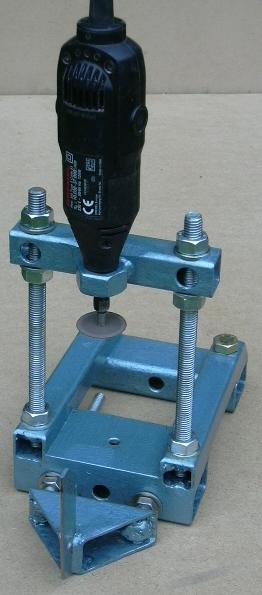
The Picture left shows the set up with the Sled fitted with the Knife Edge Follower as described in Part I. You will also notice that I am using Washers between the Nuts and the Box Section these are not indicated on the Sketches but are desirable if a Firm Fix is to be achieved without damaging the area around the holes. This illustrates the versatility of this Jig and the options are endless and therefore there are very few Tools that you could not make an Holder for. I have sketches already for a Flexible Drive Head Holder which I believe will be a more flexible option than the Router. Again using the Flexible Drive Head I am looking at making a complete Ornamental / Decorative Fly Cutter for Work Embellishment. As soon as these are finally developed and finished I will add them to these pages.
|
Drill Guide
Drilling equally spaced and accurate Holes into Turned Items is often required and with the aid of this Jig and the Indexing Head on the Lathe you can achieve this each and every time.
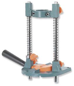
The Design is based around the Wolfcraft or Axminster Drill Guide or one of the many branded versions now appearing in the market place. for those of you not familiar with this item then the picture below should help.
 |
However
there are parts of this that you do not need such as the Handle
protruding from the left in the picture, the Orange Plastic insert in
the Base also goes.
The Spring are also redundant as is the Orange Locking Knob in the Drill Holding Collar itself, in use this Collar is always free moving. The two Guide Bars, now void of their Springs need to be permanently locked in position with the Bars Flush with the Base, I swapped the Plastic Locking Knobs with M6 Grub Screws for this. The Depth Collar, shown here on the left-hand guide post is retained but again I replaced the Locking Knob with a M6 Grub Screw. The 43mm Collar that holds the Drill uses Hexagon Head Bolts which I changed for Cap Head Screws for use with an Allen Key as this gives better access when fixing the Drill into the Jig. |
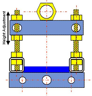
The sketch below shows the assembly mounted on the Sled viewed from the front i.e. looking at the bottom of the Drill Guide Base.
The Drill Guide is bolted to a 25 x 25 [1" sq] Box Section Cross Support which needs to be just longer than the width of the guides base, I suggest 155mm [6"] for a 145mm [5¾2] Base.
In the Base of the Drill Guide there are already two suitable holes at 126mm centers and by using two M8 bolts I just cleared the Vertical Screwed Rods from the Sled, on which this assembly is mounted, although it is very close, this was by luck and not design as I did not foresee any conflict at the time of making the Sled.
These holes are clearly visible in the picture above, a word of warning the Base is from Cast Aluminum and has a ribbed base for strength and this includes ribbing around the holes used, if the ribbing is not in contact with the Cross Support or your design requires holes drilled away from any ribbing then do not over tighten the bolts or you will distort the Base and could even Fracture it.
The Jig is used with the Pivot Arm used in a locked position on the Baseboard this can be in line or parallel with the Centre Line of the Lathe or at 90° to the CL equally it can be at any Angle between these two points.
Although Drilling is envisaged at Lathe CL height you will have the facility to work above or below center, this is not the case with the Router Holder described in Part I and when required I have used the Router in this set up for cutting above or below the Center Line, however this may require the Holding Collar to be Locked in position and therefore you will need to insert a M6 Grub Screw into the Collar Locking Hole.
Ball Cutting Jig
Balls are one of those awkward items to Turn and by far the quickest is to use a Jig and many forms of these exist some better than others, so when I started this project I soon realised I could incorporate my own design based on the Sled and do away with my less than satisfactory bought one.
Again the Sled and Pivot Bar form the basis for the Laymar Ball Jig and in conjunction with the Platform Base, Part III of this article, found I can Turn Balls of all reasonable sizes.
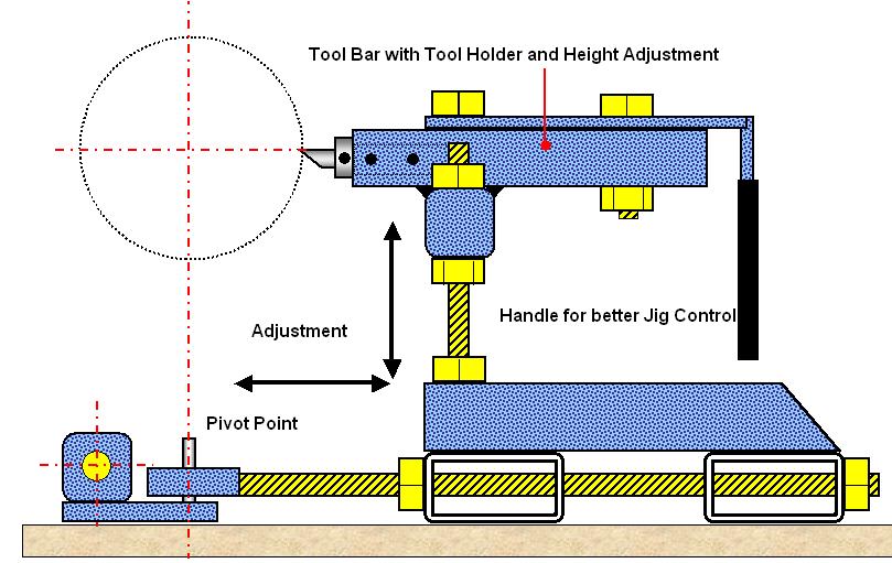
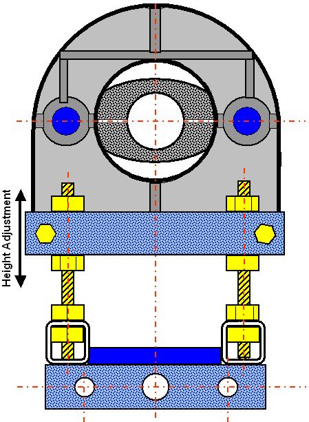
The Tool Holder has two main parts, welded together, there is again a 25 x 25 [1" sq] Box Section Cross Support drilled to suit the Vertical Screwed Rods of the Sled and a Tool Holder which was made from the same 1" Square Mild Steel Bar used to make my Boring Bar Tool.
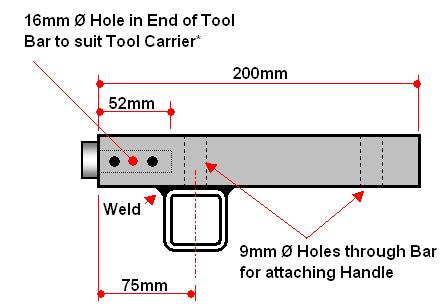
In one end I drilled a 16mm Hole to suit the Tool Holder Inserts* for the Hamlet Tool Handle, alternatively you can drill a hole to suit any HSS Cutter you may wish to use, with the Hamlet Insert you have the flexibility of choice of Tool Size.
I then drilled and tapped two holes for M6 Grub Screws in what will be the Bottom of the Tool Bar, this way the Grub Screws do not get full of Dust and Debris. These are positioned 20mm in from the end and then at 20 mm centers in the sketch above & in the drawing below they can be seen on the side of the Tool Bar for clarity.
Once all the drilling and tapping is complete you then Weld the Bar to the Cross Support with about an 75mm overhang, you can for added strength insert a M8 Bolt through the Tool Bar and Cross Support which in turn will help fix the Control Handle [25mm x 6mm MS Bar bent to shape] as shown in the sketch above.
The Vertical adjustment allows for Center or Below Center Cutting as preferred and also allows for Tool Grinding Changes to be compensated for.
The Horizontal Adjustment will fix the diameter of your Ball which can be from a few mm up to about 350mm diameter, not that I have ever gone that Big.
Copying Jig
Simply use the Ball Cutting Jig above fitted with the Tool of your choice, add the Fixed Guides described in Part I and use Base Board fitted with the Copier Profile, this will be covered in Part IV, and you have a Copying Jig.
I will show this set up in the series of Photos that will accompany Part IV of this Article.
![]() Part I of this Article.
Part I of this Article.
![]() Part III of this Article.
Part III of this Article.
![]() Part IV of this Article.
Part IV of this Article.
|
|
|
LaymarCrafts Woodturning is the Web
Site of Richard & Sheila Stapley Last update 06 May 2008
|
|
Web Site Design & Construction by Richard Stapley. |