| LaymarCrafts Woodturning | Hints & Tips |
| Lathe upgrade to Inverter Speed Control |
For some time I have been contemplating up-grading my Lathe with a Variable Speed Drive and a 0.75kW [1 HP] Motor, and having been given an Industrial Inverter [Gloat] rated at 1.5kW I set about designing a scheme that would give me all the features I desired.
But first I had to overcome some problems and also ensure I retained certain Lathe features:-
I also made some decisions on additional features that I wanted, as these were not always provided with the Lathe Manufacturers Inverter Control Option:-
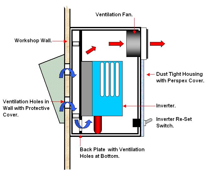
Below is the Working Diagram I came up with and this incorporates all my requirements for Control and Safety
The Inverter as I said was a Freebie, the basic specification is:-
230 Volt 1ph 50Hz Power Supply with a maximum rating of 16 Amps, Unit in Operation actually draws just over 4 Amps Maximum.
230 Volt 3ph Variable HZ [0 to 60Hz] Output with a maximum current draw of 2.8Amps under operating conditions.
It had both Control Pad or Remote Mode Selection facilities with a Forward/Reverse Selector.
I therefore needed a suitable 230Volt 3ph 50Hz TEFC Motor [Typical European Specification this may differ in the US] and decided that the Motor Upgrade on offer from my Lathe Manufacturer [Hegner] was the best option as this ensured that I could use the existing Motor Mount and Drive Pulley arrangement.
Most 3ph Motors are in fact dual Voltage and for the 230Volt you will need to Wire the Motor in Delta and you will get the necessary instructions and links to achieve this with the Motor but this should be generally as shown in the Wiring Diagram above.
For Motor Side Wiring I used a 4 x 1.5mm² Flexible Cable and for the Power Control Wiring 3 x 1.5mm² Cable, Earthing through out was done with 1.5mm² Cable.
All Control Wiring from the Inverter to Terminals 1 to 11 was done with 16/0.2 Stranded Equipment Wire and run in a separate Trunking from the Mains Cables.
You will require the following Parts if you intend to use the Remote Control Facility:-
1 off Flush N/O Push
Button, Green = Start Button.
1 off Projected N/C Push Button, Red = Stop Button.
1 off SPST 10 Amp/230V Toggle Switch = Power On/Off.
2 off SPST 1 Amp/230V Toggle Switches = Forward/Reverse and Reset, you will
require an additional Switch of the same rating if you have/intend using the Jog
Facility.
1 off 10k Linear Potentiometer and Knob for Speed Control [ check actual
requirements in the Manual supplied with your Inverter]
Suitable Box [IP56 or Better] to accommodate the above, as detailed below under
"Lathe Control Box".
1 off 7Amp/240V Relay [R1] with at least 2 N/O sets of Contacts for Lathe Run
and the Start/Stop Control.
1 off N/C Foot Switch [Breaks on Foot Pressure] if used.
All of the Switches plus the Speed Regulator were incorporated into the Lathe Control Box and for this I used a 160mm x 120mm x 90mm [6¼" x 4¾" x 3½"] Heavy Duty ABS Box Rated at IP66 for both Damp and Dust Protection
The Remote Foot/Safety Switch was retained from my previous set up and is described in earlier sections of these Hints and Tips Pages.
For Housing the various elements I have 3 Boxes:-
Box 1 houses the Inverter. This was made from MDF and is described below.
Box 2 is for the Contactor and Power Distribution, this was an old Steel Switch Box 250mm x 200mm x 120mm [ 10" x 8" x 4¾"] but any suitable Box will suffice providing it offers Sufficient Protection, in particular against the Ingress of Dust.
Box 3 [See Below] is the Lathe Control Box. and for this I used an 160mm x 120mm x 90mm [6¼" x 4¾" x 3½"] ABS Box, with a IP65 Rating which will protect the Electrics from the Ingress of Dust, providing all Cable Inlets are suitably sealed. I obtained this from my local Electrical Wholesaler.
 |
The
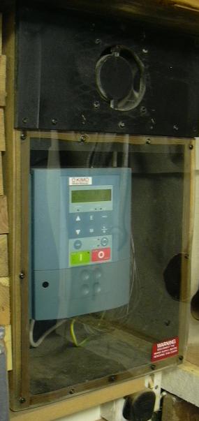
Inverter is housed in a Box constructed from MDF that is fixed to the
Wall of my Workshop, it has a Clear Perspex Cover so that the Inverter
is visible and this allows you to see the Status Lights that are
incorporated on the front panel of the Inverter.
The Box will give protection from Dust and I have allowed for Forced Ventilation via a 80mm Cabinet Fan suitable for a 230Volt Supply, this is connected to the Power Supply into the Inverter, so when the Inverter is On the Fan is also On. This draws Air from outside the Workshop via a series of Ventilation Holes drilled through the Workshop Wall and then through Holes drilled at a low level in the Mounting Plate for the Inverter. The Picture left and sketch below shows the general set up. The Perspex Cover is sealed with a Dense Draught Excluder Foam and attached with suitable Woodscrews to the Carcass of the Box. The total Wiring length from the Inverter to the Control Box is 7m [22ft] and comprises of the 3ph 3 Core Power Cable for the Motor, Live and Neutral for the Power Supply, Earths and the 9 Control wires for the Speed Regulator and other Inverter Functions. |
|
|
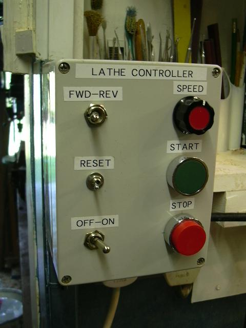
The Lathe Control Box showing details of Switch Layout and the Mounting of the Box relevant to the Lathe. |
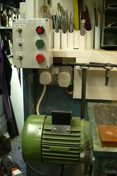
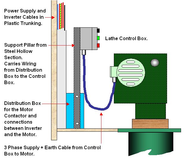
All the Power Wiring from the Inverter to the Power Supply/Distribution Box which houses the Switching Relay, Power Terminals and Wiring to ensure that I had the minimum number of Wires into the Control Box, is run in 25mm [1"] Plastic Trucking . The Control Wiring [24V] from the Inverter to the Lathe Control Switch Box is run in a separate 25mm [1"] Plastic Trucking.
The Support for the Control Box is a length of 50mm x 25mm [2" x 1"] Steel Hollow Section with a support plate welded at one end to which the Control Box is fixed.
The whole assembly is bolted onto the Distribution Box which I was conveniently able to site behind the Lathe as shown below.
By drilling a couple of 18mm Ø [¾"] holes through the side of the Distribution Box into the Hollow Section and again at the other end through the Control Box and the Hollow Section, I was able to feed the Wires through and up into the Lathe Control Box [Total of 11 wires].
Make sure you fit suitable Grommets to these Holes to protect the Wires from any Sharp Edges, and seal any possible areas where Dust may penetrate.
Before Finally Fixing everything in place make sure you can still rotate the Lathe Head if necessary and ensure the Cable to the Motor is sufficiently long enough.
A word of Warning this Project requires a reasonable understanding of Electric's and you must adhere to all Applicable Local and National Standards and Codes of Practice. You should not attempt this if you have any doubts or reservations as to your competence to do a Safe Job.
If in doubt use the services of a Competent and Accredited Electrician to advise and help you with this project.
|
|
|
LaymarCrafts Woodturning is the Web
Site of Richard & Sheila Stapley Last update 06 May 2008
|
|
Web Site Design & Construction by Richard Stapley. |