| LaymarCrafts Woodturning | Hints & Tips |
| Cam Lock Conversion for Cross Slide |
When the Clamping Mechanism of my Cross Slide [Banjo] started to show signs of wear and tare I looked into the possibility of changing to a Cam Lock method of clamping the Cross Slide in position as this appeared to be a better solution to the more traditional Center Screw and Lever found on most Commercial Type Lathes.
The principle of the Cam Lock is a very simple concept and the design I detail here should be adaptable for most Lathes with a Twin Bed Bar [Ways] arrangement.
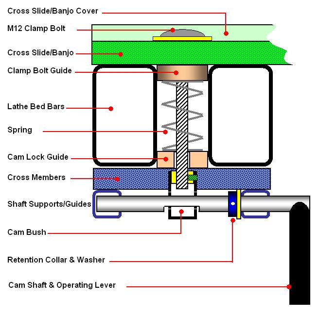
The general concept is shown above and via the detailed sketches below, the Cross Slide [Banjo] is retained and is not modified in any way, although I possibly could have utilised the original Clamp Bolt this was showing signs of wear and therefore it was changed, the Clamp Bolt Guide and Spring were the originals.
The Cam Lock is shown in the "Un-Clamped" position in the sketch and with a 1/4 [90°] turn of the lever, in either direction, the Cross Slide is locked in position, the operation of positioning and locking is single handed.
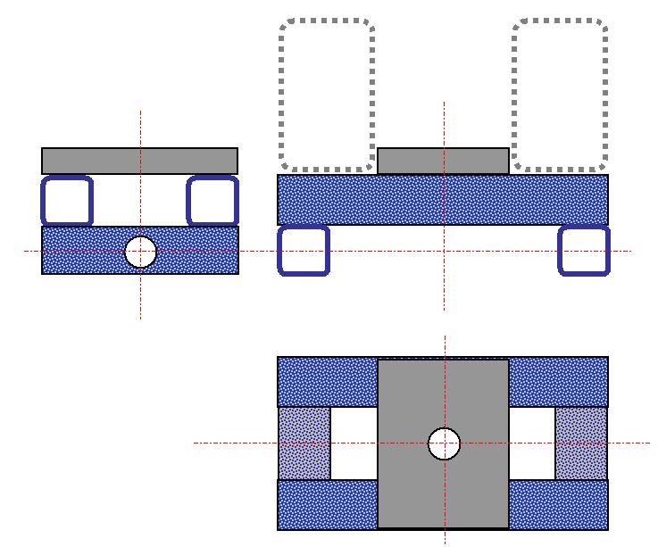
In the sketch above is the detail of the main part of the assembly, which I have called the Cam Carrier, this was assembled from 1" [25mm] square Steel Hollow Section which I Silver Soldered together but you can either Weld or Bolt the pieces together whichever suits your capabilities.
The dimensions will have to be determined to suit your particular Lathe, but to give a guide the above module measures 6" x 3½" x 2" [150 x 83 x 50mm]. The 6" dimension will be determined by the Width of your Lathe Bed and the 3½" width is determined by the size of the Tube used and the Cam Bush plus an allowance for clearance either side of the Cam Bush, likewise the height is determined by the material sizes used.
The centre guide plate needs to be an easy fit between the Bed Bars and I used a piece of 3/8" thk [10mm] Steel Plate which was bolted, using Counter Sunk Bolts, to the Cross Members, if you have Round Bars then this will need to be much thicker so as to engage positively between the Bars.
The reason for using a Square Guide Plate as opposed to the Round one, that is probably used with your old unit, is that the operating lever needs to be parallel to the Bed Bars at all times and this would not be possible with the old Circular Guide Plate.
The Guide Plate must be central and square to the cross members of the Cam Carrier and a clearance hole for the Clamp Bolt is required again centrally positioned, I used a M12 Coach Bolt [½"] and therefore the hole was 13mm Ø [9/16"].
You need to drill a series of holes into the Shaft Supports, and this is best carried out before assembling the Carrier, I used a 5/8" Ø MS Bar for the Cam Shaft [16mm] and therefore a 11/16" hole [18mm] is required, you need to drill a hole centrally right through the front support but only through the first wall of the rear support.
 |
Next
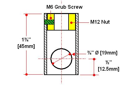
you need a Cam Bush generally as detailed left.
I again used a piece of the 1" square Steel Hollow Section into which I brazed a M12 Nut at one end and drilled a ¾" Ø hole as shown, this arrangement has shown signs of wear and I have since replaced it with a Solid Bar. I then added a M6 Grub Screw which is used to lock the Clamp Bolt in place once the whole assembly is set up and adjusted. It is important that this Grub Screw is in fact on the same center line as the ¾" hole as this will give you access for tightening the screw when required [i.e. 90° to the position shown in sketch] |
Now you require the Cam Shaft, for this I used a 8" [200mm] length of 5/8"Ø [16mm] Mild Steel Bar into which I ground [or this can be filed] the Cam as detailed below.
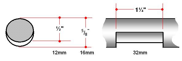
You will need to establish the exact position of the Cam in relation to the position of the Cam Bush when the Shaft is in its final position, the Cam should be as smooth as possible and should "Flow" without any steps, the exact profile is not too critical, however with too much depth you will find the Cam Lever in the "Locked" position can end up at an awkward angle.
|
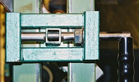
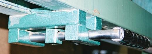
At this point I assembled the Unit in position on the Lathe in order to determine the position of the Cam Shaft Lever as I wanted it to hang vertically downward for positioning and to be horizontal when locked, once this position was established and marked the assembly was dismantled and the Lever was fixed to the Shaft. I used another length of the bar as used for the Shaft which I had welded in position by the local Blacksmith and then added a Rubber Grip. The final requirement is the Retention Collar which holds the Cam Shaft in place, for this I used a 5/8" Nut which I drilled out the thread so that it was a firm push fit on the Cam Shaft, this is locked in place via a M6 Grub Screw the location is shown in the main sketch above and can also be clearly seen in picture these pictures The Pictures show a side on view with the Cam Lever in the locked positionand a view taken from beneath with the Cam clearly visible. By using the Square Section Hollow Tube their are no Traps for Dust to collect and affect the Cam Action. |
|
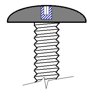
To overcome this I Drilled and Tapped the Bolt Head to take a M6 Grub Screw [or any size to suit] and therefore with a Allen Key was able to tighten or un-tighten the Clamp Bolt as required during assembly and if ever I needed to dismantle the Unit. If the Coach Bolt has a Square Section below the Head this should be rounded off to enable the Bolt to freely rotate in the Cross Slide Slot. |
|
|
|
|
LaymarCrafts Woodturning is the Web
Site of Richard & Sheila Stapley Last update 19 July 2007
|
|
Web Site Design & Construction by Richard Stapley. |