| LaymarCrafts Woodturning | Hints & Tips |
| Indexing System for the Lathe |
Both my Lathe and Chuck have a means of Indexing, but in each case the Divisions are 24 giving a Division Angle of 15° which is reasonable for small diameter work but is restrictive for the larger items.
If we take a Platter of say 100mm [4"] Ø and apply a simple "V" Groove to the Rim based on the above we will have 24 Grooves at a distance apart [at the center line] of 13.1mm [½"+] and would therefore give an equal spread of Peaks and Troughs with a nominal ½" Router Cutter.
However if we now look at a much larger Platter of say 300mm [12"] Ø we end up with the 24 Grooves spaced at 39.3mm [1½"] which, unless the Grooves are very wide, will not have such a pleasing appearance.
The Table below gives you some key Angles and the Dimension [Blue Figures] in mm between adjacent Cuts, to illustrate the above:-
| Radius R | mm | 50 | 60 | 70 | 80 | 90 | 100 | 110 | 120 | 130 | Div # |
| Angle | 6° | 5.2 | 6.3 | 7.3 | 8.4 | 9.4 | 10.5 | 11.5 | 12.6 | 13.6 | 60 |
| 12° | 10.5 | 12.6 | 14.7 | 16.8 | 18.9 | 21.0 | 23.1 | 25.2 | 27.2 | 30 | |
| 18° | 15.7 | 18.9 | 22.0 | 25.2 | 28.3 | 31.4 | 34.6 | 37.7 | 40.9 | 20 | |
| 24° | 21.0 | 25.2 | 29.3 | 33.5 | 37.7 | 41.9 | 46.1 | 50.3 | 54.5 | 15 | |
| 30° | 26.2 | 31.4 | 36.7 | 41.9 | 47.2 | 52.4 | 57.6 | 62.9 | 68.1 | 12 | |
| Radius R | mm | 140 | 150 | 160 | 170 | 180 | 190 | 200 | 210 | 220 | Div # |
| Angle | 6° | 14.7 | 15.7 | 16.8 | 17.8 | 18.9 | 19.9 | 21.0 | 22 | 23.1 | 60 |
| 12° | 29.3 | 31.4 | 33.5 | 35.6 | 37.7 | 39.8 | 41.9 | 44 | 46.1 | 30 | |
| 18° | 44.0 | 47.2 | 50.3 | 53.4 | 36.6 | 59.7 | 62.9 | 66 | 69.2 | 20 | |
| 24° | 58.7 | 62.9 | 67.1 | 71.3 | 75.5 | 79.6 | 83.8 | 88 | 92.2 | 15 | |
| 30° | 73.4 | 78.6 | 83.8 | 89.1 | 94.3 | 99.6 | 104.8 | 110 | 115.3 | 12 | |
| Radius R | mm | 230 | 240 | 250 | 260 | 270 | 280 | 290 | 300 | 310 | Div # |
| Angle | 6° | 24.1 | 25.2 | 26.2 | 27.2 | 18.3 | 29.3 | 30.4 | 31.4 | 32.5 | 60 |
| 12° | 48.2 | 50.3 | 52.4 | 54.5 | 56.6 | 58.7 | 60.8 | 62.9 | 65.0 | 30 | |
| 18° | 72.3 | 75.5 | 78.6 | 81.7 | 84.9 | 88.0 | 91.2 | 94.3 | 97.5 | 20 | |
| 24° | 96.4 | 100.6 | 104.8 | 109.0 | 113.2 | 117.4 | 121.6 | 125.8 | 130.0 | 15 | |
| 30° | 120.5 | 125.8 | 131.0 | 136.2 | 141.5 | 146.7 | 152.0 | 157.2 | 162.4 | 12 |
It can be determined from using such a Chart the positioning of any Groove, Hole or Embellishment you wish to add to any item either by Drilling, Routing or Carving, however the "Standard" 24 position Indexing facility provided with most Lathes/Chucks has a limited choice of 15° if you use every Index Hole, 30° with every 2nd Hole etc.
If however you had say a 60 Position Indexing Head you would have all the options in the above Chart and if you used a 90 Position option then you could have the choice of 90, 45, 30 15, 10, and 6 Segments or in degrees 4°, 8°, 12°, 24° and 36°.
So having convinced yourself that by having a much better Indexing System would be an advantage you have to find or make a Disc with 60, 90 locations, or whatever number you would like to use, but make sure it will divide into suitable whole numbers.
The choice is wide, you can purchase a Disc suitably Drilled or you can make one, providing the Holes are accurately drilled in the correct place, remember any inaccuracy here will be amplified the larger the diameter of the Item to be Embellished, for instance a 1° in-accuracy will represent 5.4mm at 30° & 310mm radius yet only 0.86mm at 50mm radius..
Alternatively you could use some form of Gear Wheel, or a Disc with markings and some form of clamp, the choice is wide and with a little thought and ingenuity most Woodturners should be able to source a suitable basis for an Indexing Head.
My choice was for the
Gear Wheel approach and I focused my attention on the Gear Train Wheels for a
Metal Turning Lathe, in particular the Myford which offered both 60 teeth
and 90 teeth Gear Wheels of realistic proportions.
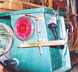
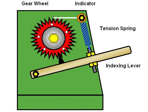
Fig 1 shows the general principle of my design of Indexing Head, firstly it must be said that a Regular Shaped Headstock [Square] as opposed to a Curved Shape offers more opportunities but this should not deter you from adapting my design if you have the latter.
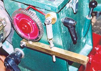
The system comprises of 3 major components, The Gear Wheel, a mounting Bush and a Indexing Lever, to this you can add, as I have a simple Position Indicator. The pictures below shows the assembly Fitted to the Lathe.
|
|
|
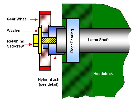
First off I carefully Drilled and Tapped the end of the Lathe Shaft [Spindle] [The Shaft on the Hegner is Solid] I chose to use an M8 Thread but the size is not critical as this is only used to clamp the Gear Wheel in place. If you do not have a Solid Shaft then you would need to use a Bolt and suitable Washers all the way through the Shaft.
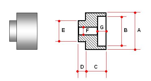
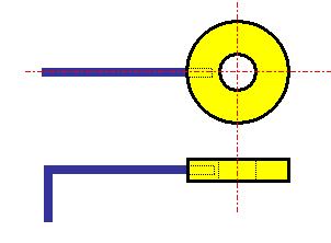
Next you require a Mounting Bush to Mount, Position and Clamp the Gear Wheel in position, the Bush was turned from Nylon, on the Lathe, using standard Woodturning Tools and Techniques,. the Bush to suit the Gear Wheel that I used and the Hegner Lathe are detailed in the sketch below.
|
|
Dimensions :-
|
The Dimensions for the Bush are dependent on the Lathe you have and the Gear Wheel you choose but the assembly will be generally as detailed below.
Next you will require a means of Indexing that is both easy to Engage and Dis-Engage yet at the same time ensuring a Solid Location so as to prevent any movement when the mechanism is being used, although Tip #50 below can offer some assistance if required.
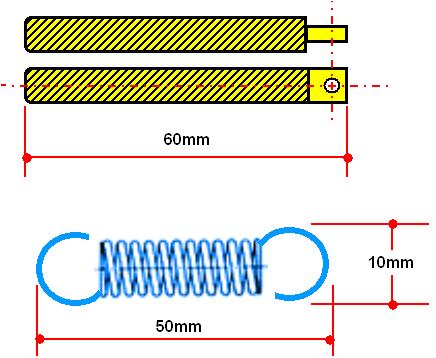
For the Index Arm I decided on a Lever Mechanism based around a Length of ½" Square Brass into which I drilled three holes, a Pivot Hole, a hole for the Index Locator and the final hole was for the Tensioning/Return Devise.
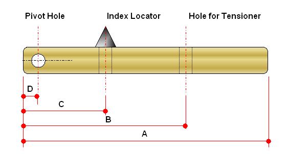
The Dimensions for the Lever Mechanism/Index Arm above are for my set up and although they work for me you should check that they will be applicable for your particular situation, the dimensions are:-
165mm
85mm
25mm
8mm
The Pivot Hole and the Tensioning bolt hole are both 6.5mm Ø for a M6 Screw and the Index Locator hole was 8mm Ø.
I used for the actual Locator a Straight Screwdriver Bit which I found almost followed the Shape of the Teeth of the Gear Wheel and this was Silver Soldered into the hole [C] as shown above in Fig.6.
|
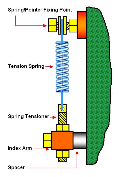
The dimensions are not important but should suit the set up on your lathe, as I started with the Spring this somewhat determined the length of the Screwed Rod. The Spring should be of reasonable strength as it is the means by which the "Locator" is held in position in the "Gear Wheel" and therefore maintains the Index Position, the Spring I used had a Coil Diameter of 10mm and a Closed Length of 28mm and an Expanded Length of 50mm [ main Spring Body Dimensions] with a Wire Diameter of 1.2mm. |
|
 |
This is fitted using the upper Tensioner Fixing Bolt and the "Bent" end of the Wire is positioned just above the Void between two Teeth of the Gear Wheel, I found this to be the most positive position for viewing the Indicator and achieving an accurate Count of the number of Teeth moved. |
You now should have all the
component parts for the Indexing Head and all that is left to do is mount the
items onto the Headstock of the Lathe, as previously indicated my Lathe benefits
from having flat surfaces and therefore it is a simple task to locate the ideal
position for the Indexing Lever simply by offering it up to the Gear Wheel
fitted to the Lathe Spindle.
The main Fixing/Pivot Screw position should be determined first and the relevant position marked off, at this point you will need to Drill and Tap a hole into the Headstock, I used an M6 Screw.
You now need to fix the Lever to the Tailstock using the M6 Screw and any Spacer /Washers you may need to ensure the Locator fits snuggly into the Gear Wheel Teeth Void, engage the Lever and Gear Wheel and loosely tighten the screw.
With the assembly now in place you can determine the location for the Spring, Tensioner [the Spring at this point needs to be 25% Expanded] see sketch & pictures above, and again mark off and then Drill and Tap a hole into the Headstock again for an M6 Screw.
At this point with just the Gear Wheel fixed in position and securely clamped I took the sharp edges off of the Gear Teeth using a File whilst slowly rotating the Lathe. You will need to reverse the Wheel if you are to chamfer both sides of the Wheel. You may be able to detect in the Photo's above some markings on the Gear Wheel, these are a series of indicators for certain positions i.e. White Lines 3 off =
Tri-Pod Position. I used a Saw or Dremel and Center Pop to make marks which are then filled with different colour Paint for clarity.
|
|
Now fix the Tensioning Assembly and the Thick Washer for the Indicator and test the function of the Assembly making any fine adjustments to the Tensioner to ensure you achieve a Solid Location and that no movement is possible of the Lathe Spindle.
Now you can determine the length and final position of the Indicator Wire which when finalised has to be fixed, in a Hole Drilled into the Thick Washer, either using Super Glue or by Soldering.
The Gear Wheel and Indexing Lever should be Removed from the Headstock when Indexing is not being used and stored away to prevent any damage that could effect the accuracy of the system.
I have used this on numerous occasions and for an outlay of less than £15 and a couple of hours work I have an accurate, very efficient and flexible Indexing System that caters for all my current requirements.
Spindle Lock
Their are occasions when I want to have the ability to use what I term "Free Hand Indexing" where I need to be able to adjust the position of the Piece in the Chuck at any position I choose and then Lock the Spindle to give me free and easy access to the Work.
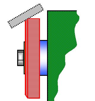
For this I devised the Spindle Lock as illustrated below:-
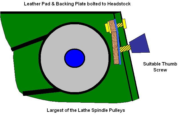
The principle is the same as for the most basic of Brakes, where a Leather Pad is forced onto a suitable surface and therefore preventing it from turning and at the same time not damaging the Surface it comes in contact with.
You
will require:-
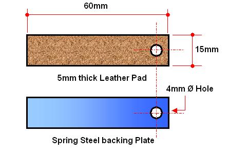
Plus suitable Drills and Taps to suit the threads for the Thumb Screw and Fixing Bolt. Firstly you will require a thick piece of Leather [5/6mm] typically to the sizes indicated, I found the local Cobbler had exactly what I wanted, and a length of Spring Steel to match the piece of Leather. Into these you need to make a hole, at one end, for the Fixing Bolt and then glue the Leather to the Spring Steel using Contact Adhesive ensuring the Holes are in line. |
|
I used for the Brake Surface the Larger of the 5 Step Pulley in the headstock of the Lathe and by offering the Assembly above up to the Pulley I was able to determine the position of both the Fixing Bolt and Thumb Screw.
I then Drilled a clearance hole for the Fixing Bolt and a suitably sized Hole Tapping to suit the M6 Lever type Thumb Screw I intended using.
Now any time I want to Lock the Spindle I simply give a couple of turns on the Thumb Screw and the Leather "Brake Pad" is forced onto the Pulley and therefore cannot rotate, when the Thumb Screw is released the Spring Steel backing ensures that the Leather Pad disengages from the Pulley.
In the Picture above showing the Indexing Head Assembly the Brake Lever can be seen top left on the front of the Headstock.
|
|
|
LaymarCrafts Woodturning is the Web
Site of Richard & Sheila Stapley Last update 19 July 2007
|
|
Web Site Design & Construction by Richard Stapley. |