| LaymarCrafts
Woodturning |
Hints
& Tips |
| Extension for Button Jaw Plates |
I use the APTC
Chuck and at the time I wanted a Button Jaw Set their was only one size
available the 250mm (10") model which was adequate but not suitable for
some of the larger Bowls / Plates I often Turn.
Some time later
Axminster introduced a Larger Button Jaw Set but this apart from being
expensive, the size at 400mm (16") would present some problems of
adjustment as the maximum swing over the Bed is 200mm and therefore I would not
be able to use the full adjustment range.
I set about making
a simple set of Extension Jaws to fit the original Jaw Plates of the 250mm
system these would have a nominal diameter of 360mm (14") with a
holding capacity up to 345mm (13½").
|
|
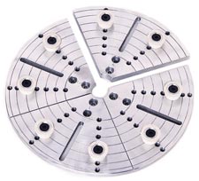
These
are the Standard 250mm Jaws c/w Buttons that I originally purchased and
these form the basis of the Extended Jaws I made.
Although my set is sized
to suit the Swing Over the Bed of my Lathe all the Sizes can be adjusted
to suit the Swing of any Lathe or for Outboard Turning almost as large as
you care to go.
I decided to use the
Holes #3 and #6 (counting from the center out) as my fixing points.
These are referred too as
the Plates in this article. |
I decided to use
20mm (¾") MDF as the Material, but you could easily use Quality Plywood or
even Aluminum if you have any available, I started with a 400mm Square onto
which I marked the Center and then using a Compass drew a 360mm Circle, and then
dissected this Circle into 4 equal Segments.
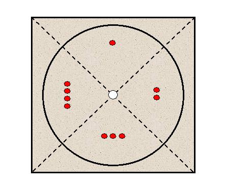 |
At
the same time I marked the Segments 1 to 4 in the correct Sequence on the
BACK of the Jaw Plates.
You also need to Drill a
Hole in the Center of the MDF with a typically a 12mm Drill.
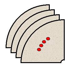
Now carefully cut
the 4 Segments on the Bandsaw or with a Jig Saw
 |
With the 4
Segments now Cut to shape you need to take the corresponding Button Jaw Plate
and place it face down onto the back of the corresponding Segment i.e. #1 MDF
Segment with #1 Aluminum Plate, so that the Straight Sides are flush and then
carefully mark through the chosen fixing points.
It is recommended
that you use 4 fixing points on each Segment, the fixings in my Plates are
Threaded for M6 Screws and I therefore would require to drill out the Holes in
each Segment to 7mm which would allow for a little bit of leeway when finally
fixing the Segment to the Plate.
Once the Holes are
Drilled you will then need to Countersink or Counter Bore the Hole to take the
Head of the Screw so that it is Flush with the Surface of the Segment, if you
are using Screws that require a Counter Bore then it may be advisable to start
with a Thicker Sheet of MDF as you do not want the point of fixing to end up to
thin.
You now Screw each
Segment to its relevant Plate and if necessary fine trim any of the Straight
edges that are not flush with the Aluminum Plates using a Belt or Disc Sander.
Now mount each
Assembly into the Chuck and using 6mm (¼") Spacers, made from Wood off
cuts, between each of the Jaw Segments, tighten the Jaws up and therefore
trapping the spacers in position.
The next operation
is to clean up the outer edge of the MDF Segments by running the Lathe at a
suitable Speed (typically 800rpm or slower) and using a Gouge true the Jaws.
The distance
between each set of Holes in the original Plates is 13mm (½"+) and I
therefore duplicated this spacing on the Extension Jaws by firstly carefully
marking out each point with a Pencil and carefully rotating the Chuck by Hand
and thus marking a Circle onto the Jaws, I repeated this for each of the 5
Circle of Holes I could accommodate.
There are two ways
you can now proceed to mark out and Drill the Holes for the Bolts to hold each
Button, either carefully mark the centre line, from the two fixing Screws used
to fix the Segment to the Plate, out to the Circumference of the Jaws, or by
using an Indexing Head and mark of at every 45°.
You can then Drill
the Holes on the Lathe with a suitable Drilling Jig or use a Bench Drill,
whichever method you use you will need to be accurate with the Hole Position as
you only have one chance and you have something like 40 Holes to Drill.
Again you can have
a choice as to what fixing method you use, I chose to use M6 Roofing Bolts
through a plain 7mm Hole with a Washer and Hexagon Nut at the rear, this does
mean you have a protrusion to the Rear of the Jaws, although this is no worse
than the way the Buttons protrude at the Front, but there is a safety issue that
you need to be aware
of.
Alternatively you
could use Threaded Inserts or even T Nuts providing the fixture is sound.
I can use a number
of Button types, the Original Buttons that came with the APTC Set or Rubber Door
Stoppers which come in various sizes, these can be shaped with a sharp knife to
give a shape for better grip or a wider grip on special projects.
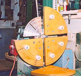 fig 1
fig 1 |
fig 2
 |
To finish off the
Jaws I gave them a couple of coats of Varnish and painted the Indents in the
back of each Segment (numbering system) Red for easy identification.
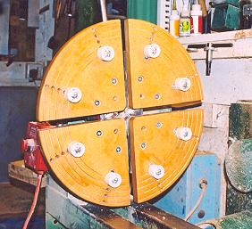
Fig1 shows how I
mount the Aluminum Jaw Plates first and then Screw each of the MDF Segments in
place due to the size it is very awkward to mount the Jaws assembled, Fig 2 shows the Jaws
fully mounted and ready for use.
These Jaws are in
constant use and I have held in excess of 200 Bowls / Platters over the last few
of years and they show little sign of any wear and tear.
Capacity
Chart for Extended Jaws
The above
Extension Jaws give the following external holding capacity when used with the Original APTC
Buttons:-
| Position |
Minimum |
Maximum |
| 1 |
220mm |
245mm |
| 2 |
245mm |
270mm |
| 3 |
270mm |
295mm |
| 4 |
295mm |
320mm |
| 5 |
320mm |
345mm |
|
LaymarCrafts Woodturning is the Web
Site of Richard & Sheila Stapley
All Content, Articles, Pictures & Diagrams as Presented are the ©
Copyright of LaymarCrafts & Richard Stapley
Last update 19 July 2007
All Rights Reserved |
|
Web Site Design & Construction by
Richard Stapley. |